
Related Manuals for Waldorf RN8100G


Summary of Contents for Waldorf RN8100G
- Page 1 I n s t a l l a t i o n a n d O p e r a t i o n M a n u a l Gas Target Top RN8100G RNB8100G RNL8100G RNLB8100G Date Purchased Serial Number...
- Page 2 MANUFACTURED BY Moffat Limited Rolleston 7675 New Zealand INTERNATIONAL CONTACTS AUSTRALIA Moffat Pty Limited Web: www.moffat.com.au E.Mail: vsales@moffat.com.au Main Office: (tel) +61 (03) 9518 3888 (fax) +61 (03) 9518 3833 Service: (tel): 1800 622 216 Spares: (tel): 1800 337 963 Customer Service: (tel): 1800 335 315...
-
Page 3: Table Of Contents
Contents Waldorf Gas Target Top RN(L)(B)8100G Target Top - 900mm. Introduction ..................... 2 Specifications ................... 3 Model Numbers Covered in this Specification General Gas Supply Requirements Gas Connection Dimensions ....................5 Weight Installation ....................9 Installation Requirements Unpacking Location Clearances... -
Page 4: Introduction
Introduction We are confident that you will be delighted with your WALDORF TARGET TOP, and it will become a most valued appliance in your commercial kitchen. To ensure you receive the utmost benefit from your new Waldorf Target Top, there are two important things you can do. -
Page 5: Specifications
Specifications Model Numbers Covered in this Specification RN[1]8100G - [2] Gas Target Top, 900mm wide. NOTE: [1]: - Model Options; - Standard. - Low Back. - Bold Front. - Low Back and Bold Front. [2] - Base Stand Options; - Bench Mount. - Cabinet Base (excluding RN8200G Series). -
Page 6: Gas Connection
Specifications - All Other Markets: Natural Gas Town Gas (**) Input Rating (N.H.G.C.) 45 MJ/hr 45 MJ/hr Supply Pressure 1.13 - 3.40 kPa 0.75 - 1.50 kPa Burner Operating Pressure (*) 1.0 kPa 0.63 kPa Gas Connection ¾” BSP Male LP Gas (Propane) Butane Input Rating (N.H.G.C.) -
Page 7: Dimensions
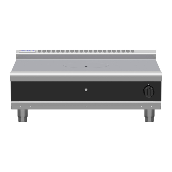
Dimensions RN(L)8100G-B Rating Plate Location Weight (Nett) RN8100G - B 160 kg. -
Page 8: Weight
Dimensions RN(L)8100G-LS Rating Plate Location Weight (Nett) RN8100G - LS 180 kg. -
Page 9: Weight
Dimensions RN(L)8100G-CB Rating Plate Location Weight (Nett) RN8100G - CB 200 kg. -
Page 10: Weight
Dimensions RN(L)8100G-RB Rating Plate Location (View through slots in door) Weight (Nett) RN8100G - RB 240 kg (Including Refrigeration Cabinet). -
Page 11: Installation
Check equipment and parts for damage. Report any damage immediately to carrier and distributor. Ensure the 4 adjustable feet are fitted with protruding centre screw. (Not fitted on RN8100G - RB Models). Report any deficiencies to distributor who supplied appliance. -
Page 12: Clearances
Operation Manual supplied with Refrigeration Cabinet. Assembly NOTE: Leg Stand Model (RN8100G-LS), will require assembly. Refer to 'Leg Stand Models Only' information shown below for assembly instructions. All Models are delivered completely assembled. No further assembly is required, with the exception of Leg Stand Model (RN8100G-LS), this will require assembly. - Page 13 Installation Rear Adjustable Feet, fitting:- Secure rear of base tray to rear target top legs by screwing two adjustable feet supplied, into base of rear target top legs. Secure each adjustable foot, hand Target tight. Rear Rollers, fitting:- Fit rear leg securing bolts up through Leg Mount Points centre of rear leg housings to secure...
-
Page 14: Fitting Adjustable Feet / Rear Rollers To Cabinet And Refrigeration Bases
Installation Fitting Adjustable Feet / Rear Rollers to Cabinet and Refrigeration Bases. Rear Adjustable Feet, fitting:- Raise appliance from floor by approximately 75mm using suitable lifting equipment (i.e. Cabinet / Palletiser / Forklift) to allow rear rollers to be Refrigeration removed. -
Page 15: Gas Connection
Gas Connection NOTE: ALL GAS FITTING MUST ONLY BE CARRIED OUT BY AN AUTHORISED PERSON. Waldorf Target Tops do not require an electrical connection, as they function totally on gas supply only. It is essential that gas supply is correct for target top to be installed and that adequate supply pressure and volume are available. -
Page 16: Commissioning
Installation Check gas operating pressure is as shown in the ‘Specifications’ section. NOTE: Measure Burner operating pressure at target top hob manifold test point with target top burner (Inner and outer ring) operating at full setting. Verify operating pressure remains correct. NOTE: This appliance is fitted with adjustable feet to enable appliance to be positioned securely and level. -
Page 17: Operation
/ operator. Waldorf target tops have been designed to provide simplicity of operation and 100% safety protection. Improper operation is almost impossible, however bad operation practices can reduce the life of the target top and produce a poor quality product. -
Page 18: Lighting Pilot Burner
Operation Lighting Pilot Burner Remove centre casting with casting removal tool. Push-in control knob and rotate anti-clockwise to PILOT position. With control knob depressed, manually light pilot burner located in front of main burner. Hold in control knob for approximately 10 to 15 seconds, then release. Pilot burner should remain alight. -
Page 19: Cleaning And Maintenance
Cleaning and Maintenance General Caution Always turn ‘Off’ gas supply before cleaning. This appliance is not water proof. Do not use water jet spray to clean interior or exterior of this appliance. Clean the Target Top regularly. A clean appliance looks better, will last longer and will perform better. -
Page 20: Periodic Maintenance
Cleaning and Maintenance c. DO NOT use water on castings while they are still hot as cracking may occur. Should it be necessary to clean castings, allow them to cool and then remove for cleaning. Clean using a soft cloth moistened with a mild detergent and hot water solution and a scrubbing brush. Dry thoroughly with a dry cloth. -
Page 21: Fault Finding
Fault Finding This section provides an easy reference guide to more common problems that may occur during operation of your equipment. The fault finding guide in this section is intended to help you correct, or at least accurately diagnose problems with your equipment. Although this section covers most common problems reported, you may encounter a problem not covered in this section. -
Page 22: Gas Conversion And Specifications
Gas Conversion and Specifications Conversion Procedure Caution Ensure Appliance is isolated from gas and electrical supplies before commencing servicing. NOTE: These conversions should only be carried out by qualified persons. All connections must be checked for leaks before re-commissioning appliance. ... -
Page 23: Gas Regulator
Gas Conversion and Specifications Pilot Burner Main Burner NOTE: Ensure pilot burner and thermocouple are Ignition Port correctly located and pilot burner aligns with Thermocouple main burner ignition port. (Refer to figure 2± 2.0 18± 2.0 opposite for correct fitting and alignment dimensions). - Page 24 Gas Conversion and Specifications Gas Type Identification Label On completion of gas conversion, replace gas type identification label, located at:- - Rear of the unit, above the gas connection. - Beside the Rating Plate. Commissioning Before leaving the installation; Check all gas connections for leakages using soapy water or other gas detecting equipment. Warning O NOT USE A NAKED FLAME TO CHECK FOR GAS LEAKAGES Carry out a ‘Commissioning’...
-
Page 25: Gas Specifications
Gas Conversion and Specifications Gas Specifications - Australia: Natural Gas LP Gas (Propane) Main Burner Injector (Inner Ring) Ø 1.70mm Ø 1.10mm Main Burner Injector (Outer Ring) Ø 2.60mm Ø 1.55mm Pilot Burner Injector 0.35 0.25 Burner Aeration Screw X (Inner) 25mm 25mm Burner Aeration Screw Y (Outer) - Page 26 Gas Conversion and Specifications - United Kingdom: Category: 2H3P. Flue Type: Natural Gas (G20) Propane (G31) Main Burner Injector (Inner Ring) Ø 1.70mm Ø 1.10mm Main Burner Injector (Outer Ring) Ø 2.60mm Ø 1.55mm Pilot Burner Injector 0.35 0.25 Burner Aeration Screw X (Inner) 25mm 20mm Burner Aeration Screw Y (Outer)
- Page 27 Gas Conversion and Specifications - All Other Markets: Natural Gas Town Gas (**) Main Burner Injector (Inner Ring) Ø 1.70mm Ø 4.20mm Main Burner Injector (Outer Ring) Ø 2.60mm Ø 6.30mm Pilot Injector 0.35 0.70 Burner Aeration Screw X (Inner) 25mm 20mm Burner Aeration Screw Y (Outer)
-
Page 28: Replacement Parts List
Replacement Parts List Replacement Parts List IMPORTANT: Only genuine authorized replacement parts should be used for servicing and repair of this appliance. Instructions supplied with parts should be followed when replacing components. For further information and servicing instructions, contact your nearest authorized service branch (contact details are as shown on reverse of front cover of this manual). - Page 29 Gas Conversion Kits Gas Type to Convert to:- Model Nat. Gas Butane Town Gas (*) RN8100G 231972 231971 231973 N/A (*) NOTE: (*) Town Gas Option is only available with specific ex-factory built Town Gas models, which can also be converted to any other gas.
Need help?
Do you have a question about the RN8100G and is the answer not in the manual?
Questions and answers