Table of Contents
Advertisement
Quick Links
Advertisement
Table of Contents

Related Manuals for Planet PL-701


Summary of Contents for Planet PL-701
- Page 1 500Mbps Powerline Ethernet Bridge PL-701...
-
Page 2: Fcc Compliance Statement
PLANET Technology. Disclaimer PLANET Technology does not warrant that the hardware will work properly in all environments and applications, and makes no warranty and representation, either implied or expressed, with respect to the quality, performance, merchantability, or fitness for a particular purpose. -
Page 3: Ce Mark Warning
WEEE s eparately. Trademarks The PLANET logo is a trademark of PLANET Technology. This documentation may refer to numerous hardware and software products by their trade names. In most, if not all cases, these designations are claimed as trademarks or registered trademarks by their respective companies. -
Page 4: Table Of Contents
Table of Content CHAPTER 1: INTRODUCTION ............5 1.1 O ................... 5 VERVIEW 1.2 F ................... 5 EATURES 1.3 S ................6 PECIFICATION 1.4 P ..............6 ACKAGE ONTENTS 1.5 S .............. 6 YSTEM EQUIREMENTS 1.6 W ................9 IAGRAM CHAPTER 2: INSTALLING ............. -
Page 5: Chapter 1: Introduction
Ethernet cabling to share network. It is simply by plugging the PL-701 into the wall anywhere in the house or office. The 128-Bit AES data encryption improves the security and reliability, to protect the data leaked by someone else. -
Page 6: Specification
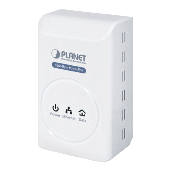
PL-701 x 1 (PL-701 x 2 for PL-701-KIT) CD ROM x 1 (User’s Manual, Quick Guide and Utility) RJ-45 Cable x 1 (RJ-45 Cable x 2 for PL-701-KIT) Quick Installation Guide x 1 1.5 System Requirements Windows 98SE, Windows 2000, Windows ME, Windows XP... - Page 7 Outlook LED Definition Color Behavior Description Green Power is on System enters the power save mode. System is resetting. Green Blink Power System is in the process of security setup. Power is off. The device is connecting to other Green devices via the Ethernet interface but not communicating with them.
- Page 8 Color Behavior Description The device has connected to the power line network. The Data LED color will vary according to the physical rate. Green/Red Green: Link Rate > 40 Mbps Orange: 20 Mbps< Link Rate <40 Mbps Red: Link Rate< 20 Mbps Data When the device is scanning other PLC devices, the Data...
-
Page 9: Wire Diagram
1.6 Wire Diagram... -
Page 10: Chapter 2: Installing
Chapter 2: Installing 2.1 Overview The installation of 500M Ethernet Bridge will only take minutes. No need to set up long wires through out the house, just simply install the utility, and physically plug the unit into the wall outlet, then to connect RJ-45 to the computer. Users can select to adjust its security functions and the platform of the network after the installation. - Page 11 Please take a moment to read the license agreement now. If you accept the terms below, click ”I Agree”. Then “Next“. Otherwise click” Cancel”. This section allows you to change the default directory where the program is installed. Or go ‘Back’. If you don’t want to change it, click on Next to continue the installation.
- Page 12 Please click on ‘Next’ to confirm the installation. Powerline Utility is being installed, and please waits for installation.
- Page 13 This screen shows that the installation was completed successfully. Click on Close to exit the wizard.
-
Page 14: Chapter 3: Configuration
Chapter 3: Configuration 3.1 Overview The PL-701 uses 128-bit AES encryption to block outside access. The key is set by using the Configuration Utility on the CD. By default, the protection is enabled, however, it is recommended to change the default network password. All your Powerline devices must use the same network password in order to be connected together. - Page 15 If you do not see ANY unit in the device status but the Powerline device does exist, try to unplug all devices and plug them back. Note Meanwhile, please make sure the cable is the right type and working correctly. If all seems to be correct, and you still receive nothing in the Device window, try rebooting your computer.
- Page 16 If there are units in the home network, but nothing displays in this Note Network scan, try to unplug all devices, and plug them back (Only do this with the units that you do not view in the network screen, you don’t have to do this with all units.) If the problem persists, try to move the unit closer to this current unit (adjacent plugs on the same wall socket is most preferable).
-
Page 17: Privacy
3.3 Privacy Setting Up Security on a Local Powerline device The Privacy tab will allow you to change the Network Password to the unit that is currently connected to this computer. This network password encrypts all data that is sent from this unit using 128-bit data encryption standard (AES). Every unit on your home network MUST have the same Network Note Password for connectivity to be established throughout your home. - Page 18 Setting Up Security on a Network Powerline device The Privacy Tab will allow users to use one primary computer to control the Network Password of all units on the home network. You will have to go back to the Main Tab first then find the DEK (Device Encryption Key) Key located on the bottom of each device.
- Page 19 The DEK is unique for EACH Pow erline device. To use this you Note will need to input the DEK for each unit.
-
Page 20: Diagnostics
3.4 Diagnostics The Diagnostics screen shows system information and a history of all devices seen. Diagnostics Screen The upper panel shows technical data concerning software and hardware on the host computer used to communicate over HomePlug. It shall include the following:... -
Page 21: Security Button
The lower panel contains a history of all remote devices. Devices are shown here regardless of whether or not they are on the same logical network. Device Name MAC Address Password Rate(Tx/Rx) Network Last Seen ... - Page 22 Use random value of security network (Network AB) 1. Press the security button on Powerline (a) more than 10 seconds until all LEDs off. 2. Press the security button on Powerline (a) during 1~3 seconds. 3. Press the security button on Powerline (b) during 1~3 seconds. 4.
-
Page 23: Reset Button
The procedure is as follows: 1. Hold the reset Button down while Power On for a few seconds. 2. Release the reset button. 3. All the LEDs will off, and then start again. 4. PL-701 is now using the factory default values. -
Page 24: Appendix A Specifications
Appendix A Specifications Chipset Atheros AR7400 Compliant with HomePlug AV 1.1 Protocol Co-existing with existing HomePlug 1.0 Windows 98SE, Windows 2000, Windows ME, Windows System Support XP 32/64 bit, Windows Vista 32/ 64bit and Windows 7 PLC Rate 500 Mbps Modulation Band 2MHz~68MHz Modulation...
Need help?
Do you have a question about the PL-701 and is the answer not in the manual?
Questions and answers