Table of Contents
Advertisement
Quick Links
Advertisement
Table of Contents

Related Manuals for Planet VIP-281SW


Summary of Contents for Planet VIP-281SW
- Page 1 User’s Manual VIP-281SW 802.11n Wireless VoIP Router - 1 -...
-
Page 2: Ce Mark Warning
PLANET has made every effort to ensure that this User’s Manual is accurate; PLANET disclaims liability for any inaccuracies or omissions that may have occurred. - Page 3 Revision User’s Manual for PLANET 802.11n Wireless VoIP Router: Model: VIP-281SW Rev: 1.0 (2011, February) Part No. EM-VIP-281SW_v1 - 3 -...
-
Page 4: Table Of Contents
TABLE OF CONTENTS Chapter 1 Introduction....................6 Overview ......................6 Package Content ....................7 Physical Details ....................7 Physical Interface & Button....................8 Chapter 2 Preparations & Installation..............9 Physical Installation Requirement ..............9 Keypad commands ......................10 Chapter 3 Network Settings ...................13 Configuring and monitoring your Router from web browser.......13 Overview on the web interface of Router................ - Page 5 Logout ..........................63 Appendix A Voice communication samples...........64 Peer to peer (P2P) mode ..................... 64 Case 2: (Peer-to-Peer mode) VIP-281SW Port 1 to Port 2 communications ...... 65 Case 3: SIP Proxy mode...................... 66 Case 4: Call Forward Feature....................69 Case 5: VIP-281SW register with IPX-1900 via WAN port ..........
-
Page 6: Chapter 1 Introduction
Access Point (AP) function for flexible wireless communication. With advanced router and VoIP DSP processor technology, the VIP-281SW is able to make calls via SIP proxy voice communications plus the IP sharing and the QoS mechanism. -
Page 7: Package Content
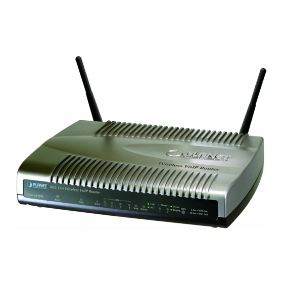
802.11n Wireless VoIP Router Power adapter Quick Installation Guide User’s Manual CD RJ-11 cable x 2 RJ-45 cable x1 Antenna x2 Physical Details The following figure illustrates the each panel of VIP-281SW Front Panel of VIP-281SW Rear Panel of VIP-281SW - 7 -... -
Page 8: Physical Interface & Button
Physical Interface & Button Front Panel LED Indicators State Descriptions Router is power ON Router is power Off Router network connection established Flashing Data traffic on cable network Waiting for network connection LAN is connected successfully Flashing Data is transmitting Ethernet not connected to PC The Wi-Fi Protected Setup function is starting. -
Page 9: Chapter 2 Preparations & Installation
TCP/IP protocol must be installed on all PCs. For Internet Access, an Internet Access account with an ISP, and either of a DSL or Cable modem Administration Interface PLANET Router provides GUI (Web based, Graphical User Interface) and utility for machine management and administration. Web configuration access You will connect to SIP Router via your web browser automatically. -
Page 10: Keypad Commands
The default IP address of LAN port is 192.168.0.1. (The WAN port is DHCP client mode.) You also could open your web browser, and insert http://192.168.0.1 in the address bar of your web browser to logon Router web configuration page. To start Router web configuration, you must have one of these web browsers installed on computer for management •... - Page 11 The system will be reset to Factory Reset None factory default value and #198# reboot automatically. Following keypad commands can be used to display the network settings enabled on Router via voice prompt. IVR Menu Choice Machine operation Notes IVR will announce the current IP address of Check LAN port IP Address #120# the LAN port.
- Page 12 Disable call waiting None Disable Call waiting #139# Forward Type: #140+Forward 1: Immediate Forward For example: #1401101# Forward Settings type+Forward 2: Busy Forward Immediate Forward to 101 Phone Number# 3: No answer Forward Disable Forward Settings None #141# For example: #1501# Select Default Realm 0: Realm 1, 1: Realm 2 #150#...
-
Page 13: Chapter 3 Network Settings
Chapter 3 Network Settings Configuring and monitoring your Router from web browser The Router integrates a web-based graphical user interface that can cover most configurations and machine status monitoring. Via standard web browser, you can configure and check machine status from anywhere around the world. -
Page 14: Network Oprtation Mode
Router login prompt screen When users login the web page, users can see the general information like company…etc in this main page. VoIP Router main page Network Oprtation Mode You can setup different modes to WAN and LAN interface for NAT, Bridging and Wireless ISP function - 14 -... -
Page 15: Wan Interface Setup
In this mode, the device is supposed to connect to internet via ADSL/Cable Modem. The NAT is enabled and your PC in LAN port shares the same IP to ISP through WAN port. The connection type can be setup in WAN page by using PPPOE, DHCP client, PPTP client, static IP or L2TP. - Page 16 Connection Type Description – Static IP Set WAN interface as Static IP mode. Static IP WAN IP Address of the Router IP Address Default : 192.168.0.1 WAN mask of the Router Subnet Mask Default : 255.255.255.0 Gateway Address of the Router Default Gateway Default : 192.168.0.254 Set MTU (maximum transmission unit) size...
- Page 17 Check to enable UPnP function Enable UPnP Default : Disable Check to enable the IGMP Proxy function Enable IGMP Proxy Default : Enable If accept ICMP response via WAN port Enable Ping Access on WAN Default : Enable If accept be accessed to Web Management Interface via WAN Enable IPSec pass through on port VPN connection...
- Page 18 Set WAN interface as DHCP mode. DHCP Client Select to attain DNS automatically from server or user wants to Attain DNS Automatically / set DNS manually. Set DNS Manually Default : Set DNS Manually Connection Type Description – PPPoE - 18 -...
- Page 19 Set WAN interface as PPPoE mode. PPPoE Set user name of PPPoE connection User Name Default : Null Set password of PPPoE connection Password Default : Null Set Service Name of PPPoE for description Service Name Default : Null Set PPPoE connection type to be Continuous/ Connect on Demand/ Connection Type Manual.
- Page 20 Set LAN interface as PPTP/L2TP mode. PPTP Set IP type if Dynamic IP or Static IP at PPTP/L2TP connection. Mode Default : Dynamic IP WAN IP Address of the Router at Static IP type. IP Address Default : 0.0.0.0 Subnet Mask WAN Mask of the Router at Static IP type.
-
Page 21: Lan Interface Setup
LAN Interface Setup This page is used to configure the parameters for local area network which connects to the LAN port of your Gateway. Here you may change the setting for IP address, subnet mask, DHCP, etc.. LAN IP Address of the Router IP Address Default : 192.168.0.1 Subnet Mask... - Page 22 Set three alternatives Domain Name Server for LAN interface. Domain Name Default : Null Spanning Tree Protocol. You can select Enable or Disable. 802.11d Spanning Tree Default : Disable Show the egress and ingress total network traffic for each WAN Port Bandwidth Manager and LAN ports (WAN / LAN ports)
-
Page 23: Chapter 4 Wireless Settings
Chapter 4 Wireless Settings Basic Settings This page is used to configure the parameters for wireless LAN clients who may connect to your Access Point. Here you may change wireless encryption settings as well as wireless network parameters. Disable Wireless LAN Enable or disable the wireless LAN. - Page 24 - AP: The AP functions as a wireless hub to which wireless clients Mode can connect. The clients must make sure that they are configured to match the AP’s wireless settings. The AP must be connected to switch or other LAN segment patch cable. - Client: In this mode the Router is used to access the Wireless Service Provider network by connecting wirelessly to the remote (Outdoor AP).
-
Page 25: Advanced Settings
The short of Wi-Fi Multi-Media, it will enhance the data transfer performance of multimedia contents when they’re being transferred over wireless network. Default : Enable (Unavailable) The Data Rate is the rate of data transmission for 802.11b/g/n Data Rate clients. The Router will use the highest possible selected transmission rate to transmit the data packets. - Page 26 “Fragment Threshold” specifies the maximum size of packet during Fragment Threshold the fragmentation of data to be transmitted. If you set this value too low, it will result in bad performance. Default : 2346 When the packet size is smaller the RTS threshold, the access point RTS Threshold will not use the RTS/CTS mechanism to send this packet.
-
Page 27: Security Setup
Inter-Access Point Protocol is a recommendation that describes an IAPP optional extension to IEEE 802.11 that provides wireless access-point communications among multivendor systems. Default : Enable It is recommended to enable the protection mechanism. This Protection mechanism can decrease the rate of data collision between 802.11b and 802.11g wireless stations. - Page 28 If assigned multiple AP feature, you could choose the SSID that want to Select SSID setup encryption function. Select the data privacy algorithm you want. Enabling the security can Encryption protect your data while it is transferred from one station to another. Default : Disable Check Box was used to switch the function of the 802.1X.
- Page 29 RADIUS server. - WPA2 When sele ct the WPA function, the Wireless user must authenticate to this router first to use the Network service. RADIUS Server IP address or the 802.1X server’s domain-name. If you select HEX, you have to fill in 64 hexadecimal (0, 1, 2…8, 9, A, B…F) digits If ASCII, the length of Pre-share key is from 8 to 63.
-
Page 30: Access Control
Access Control If you choose 'Allowed Listed', only those clients whose wireless MAC addresses are in the access control list will be able to connect to your Access Point. When 'Deny Listed' is selected, these wireless clients on the list will not be able to connect the Access Point. WDS Settings Wireless Distribution System uses wireless media to communicate with other APs, like the Ethernet does. -
Page 31: Site Survey
Site Survey This page provides tool to scan the wireless network. If any Access Point or IBSS is found, you could choose to connect it manually when client mode is enabled. WPS Settings Wi-Fi Protected Setup (WPS) is the simplest way to build connection between wireless network clients and this wireless router. - Page 32 Check this box to disable WPS function, uncheck it to enable WPS. Disable WPS If the wireless security (encryption) function of this wireless router is WPS Status properly set, you’ll see ‘Configured’ message here. If wireless security function has not been set, you’ll see ‘unConfigured’. This is the WPS PIN code of this wireless router.
- Page 33 4. If you see the wireless client in the list, WPS-PBC setting is successful. - PIN (as register) setup step: 1. Select Config Mode: “Registrar” on Router. 2. Fill the PIN code of the other device (as Enrollee that support WPS-PIN setting) into the “configure via Client Pincode”...
-
Page 34: Wireless Schedule
Wireless Schedule This page allows you setup the wireless schedule rule. Please do not forget to configure system time before enable this feature. - 34 -... -
Page 35: Chapter 5 Firewall Settings
Chapter 5 Firewall Settings Port Filtering Entries in this table are used to restrict certain types of data packets from your local network to Internet through the Gateway. Use of such filters can be helpful in securing or restricting your local network. IP Filtering Entries in this table are used to restrict certain types of data packets from your local network to Internet through the Gateway. -
Page 36: Mac Filtering
MAC Filtering You can filter Internet access for local clients based on MAC Address. The MAC address filter enables you to allow or restrict specified nodes from communicating with other nodes. - 36 -... -
Page 37: Port Forwarding
Port Forwarding The Port Forwarding allows you to re-direct a particular range of service port numbers (from the Internet/WAN Ports) to a particular LAN IP address. It helps you to host some servers behind the firewall. URL Filtering URL filter is used to deny LAN port users from accessing the internet. Block those URLs which contain keywords listed below. -
Page 38: Dmz
A Demilitarized Zone is used to provide Internet services without sacrificing unauthorized access to its local private network. Typically, the DMZ host contains devices accessible to Internet traffic, such as Web (HTTP) servers, FTP servers, SMTP (e-mail) servers and DNS servers. Entries in this table improve your online gaming experience by ensuring that your game traffic is prioritized over other network traffic, such as FTP or Web. -
Page 39: Chapter 6 Sip Settings
Chapter 6 SIP Settings Phone 1 / Phone 2 This page is used to configure the parameters for SIP registration information. Here you also could setup the other functions like Call Forward, Voice Codec, Speed Dial and others. After finish all the settings, press the button to activate the new settings, or press the button to cancel the changes. - Page 40 Set Router Phone display name for caller ID information. Display Name Default : Null Set registering Phone number. Line Number Default : Null If Proxy server needs registration authentication please input Register Name Login ID here. Default : Null If Proxy server needs registration authentication please input Register Password password here.
- Page 41 - Call Forward This is unconditional forward setting. All incoming call will be All Forward forwarded to specified number. Check to enable immediate forward function. Default : Off Enter the assigned number for Immediate forward. All Fwd No. Default : Null Check to enable Busy Forward function.
- Page 42 Abbreviated Dial (Phonebook) access code. Input this number Abbreviated Name and followed by # can dial out assigned phone number. Set phone number for Router to make speed dial. Phone Number - Dial Plan Select to enable (On) or disable (Off) prefix replace function. Replace prefix code Default : Off Set prefix replace rule.
- Page 43 If user set Auto Prefix number, all number dialed out will be added Auto Prefix with this prefix number. Available parameters are “0~9”, “#”, “*”.For example, user set Auto Prefix as 02, number 87654321 will be dial out as 02 87654321. Default : Null User can set special access code to disable Auto Prefix function in Prefix Unset Plan...
- Page 44 - SIP Advanced Set local SIP listening port. SIP Port Default : 5060 Set RTP port for sending voice data. Media Port Default : 9000 Select DTMF Relay to be In band, RFC 2833, or SIP INFO. DMTF Relay Default : Inband If user select DTMF as RFC 2833 type, here can modify RFC RFC2833 Payload Type 2833 payload type.
- Page 45 - NAT Traversal Check to enable STUN function. Stun Default : Disable If user enables STUN function, please input STUN Server Stun Server Addr address. Default : Null If user enables STUN function, please input STUN Server port. Stun Server Port Default : 3478 - Codec Set codec priority sequence.
- Page 46 - T.38 (FAX) Check to enable T.38 function. T.38 Default : Disable Set T.38 port for FAX. T.38 Port Default : 9008 - DSP – Digital Singnal Process Options - 46 -...
- Page 47 Check to enable VAD (Voice Activity Detection) function. Default : Disable Select caller ID mode as FSK (Bellcore), FSK (ETSI), FSK (BT), Caller ID Mode FSK (NTT), or DTMF from Phone to send out. Default : DTMF Check to send FSK Date and Time to caller ID display device. FSK Date &...
- Page 48 Hot Line Number Use Hot Line Default : Disable Set the destination number for Hot Line function. Hot Line Number Default : Null - DND (Don’t Disturb) You can select 3 mode of DND. The call will be always rejected if DND Mode Always is selected.
-
Page 49: Tone
Tone Parameters This page is used to configure the Tone country, or setup the custom tone parameters. - Select Country User can select country to specify tone parameters (Dial Tone, Country Ring Tone, Busy Tone, and Waiting Tone). If user wants to set tone manually, please select CUSTOMER. - Page 50 - Tone Parameters Set first set of tone frequency in Hz. Freq1 Default : 0 Set second set of tone frequency in Hz. This frequency is Freq2 optional. Default : 0 Set volume level of Freq1 in dB (-7~-10). Please set this Gain1 parameter under zero and suggested to set between –7 to –10.
-
Page 51: Other
Set cadence time for tone not to play in ms. For example, if set CanOff CanOff as 100, the tone will stop playing for 100ms. Default : 0 Other This page is used to configure the function key and other parameters. - Function Key Set call transfer function key. -
Page 52: Sip Qos
Set off-hook alarm time. If phone set has been off-hook, after this Off-Hook Alarm Time time, from phone sett will hear alarm. Default : 30 - FXS Pulse Dial Detection If your telephone set is pulse type, you can enable this option and define the interdigit pause duration parameters for operation priority. -
Page 53: Chapter 7 Management
Chapter 7 Management Status In this page can show the current status and some basic settings of the Router. Statistics This page shows the packet counters for transmission and reception regarding to Ethernet networks. - 53 -... -
Page 54: Ddns
DDNS Dynamic DNS is a service, which provides you with a valid, unchanging, internet domain name (an URL) to go with that (possibly ever-changing) IP-address. Before setting this page, you should click below link to DynDNS or TZO to apply an account for DDNS. Check to enable DDNS function. -
Page 55: Time Zone Setting
Time Zone Setting You can maintain the system time by synchronizing with a public time server over the Internet. Input current time manually. Current Time Select local time zone according to location. Time Zone Select Check to enable NTP update. Once this function is enabled, Enable client Router will automatically update current time from NTP server. -
Page 56: Snmp Management
Check to enable DoS function. Enable DoS Prevention User may set other related configurations about DoS below. SNMP Management This page is used to configure the parameters for SNMP. SNMP is a widely used protocol for monitoring the health and welfare of network equipment (eg. routers), computer equipment and even devices like UPSs. -
Page 57: Log
This page can be used to set remote log server and show the system log. - 57 -... -
Page 58: Upgrade Firmware
Check to enable log function. Enable Log Select which log you want to check. Related information will System all/Dos be shown at below. Upgrade Firmware This page allows you upgrade the Router firmware to new version. Please note, do not power off the device during the upload because it may crash the system. - Page 59 - Auto Firmware Update The Router can update new firmware file automatically by the Auto Firmware Update function. There are TFTP / FTP and HTTP three ways to provide the auto Mode upgrade function. Input the TFTP Server address, and it could input the IP or TFTP Server Address Domain Name form.
-
Page 60: Save / Reload Settings
The Router will according to the below ways to check the new Check new firmware firmware. - Power On: The machine will check the new firmware when power on and following the scheduling date and time. - Scheduling: The machine will follow the scheduling date and time to check the new firmware. -
Page 61: Password Setup
Password Setup This page is used to set the account to access the web server of Router. Empty user name and password will disable the protection. Enter user name. User Name Input password for this user. New Password Confirm password again. Confirmed Password - 61 -... -
Page 62: Chapter 8 Utility
Chapter 8 Utility Ping Watchdog Setup This page is used to configure the parameters for Ping Watchdog which pings to IP address every time interval. System will reboot when failing to ping the IP address 3 times. Ping Test This page is used to configure the parameters for Ping Test which pings to IP address or Domain Name. -
Page 63: Traceroute
Traceroute This page is used to configure the parameters for Traceroute which traces to IP address or Domain Name. Reboot Press Reboot to reboot system. Please wait for a few minutes and reload web page again. Logout This page is used to logout. - 63 -... -
Page 64: Appendix A Voice Communication Samples
Appendix A Voice communication samples There are several ways to make calls to desired destination in Router. In this section, we’ll lead you step by step to establish your first voice communication via keypad and web browsers operations. Peer to peer (P2P) mode Assuming there are two routers in the network, the WAN port IP address are 192.168.0.1 and 192.168.0.2 Test the scenario:... -
Page 65: Case 2: (Peer-To-Peer Mode) Vip-281Sw Port 1 To Port 2 Communications
Case 2: (Peer-to-Peer mode) VIP-281SW Port 1 to Port 2 communications Supposing one VIP-281SW connects to two telephones, just pick up phone 1 and dial ‘192*168*0*1**5062’, phone 2 will ring. Analog telephone sets are connected to the phone (RJ-11) ports of VIP-281SW respectively Test the scenario: 1. -
Page 66: Case 3: Sip Proxy Mode
Client mode, and fill in the SSID of UMG-2000 (UMG_WIFI). In the setting page, please insert the account/password information obtained from your service provider (in this sample, we’re using PLANET UMG-2000 as the IP PBX server for SIP account, call authentications), and then the sample configuration screen is shown below:... - Page 67 It also could access to “Wireless Site Survey” menu to survey the wireless access connection and connect to UMG-2000. STEP 3: To assign the LAN port network parameters as 172.16.0.1 (IP Address) / 255.255.0.0 (Subnet Mask). - 67 -...
- Page 68 Please log in Router-A via web browser, find to the SIP item. In the setting page, please insert the account/password information obtained from your service provider (in this sample, we’re using PLANET UMG-2000 as the IP PBX server for SIP account, call authentications), and then the sample configuration screen is shown below:...
-
Page 69: Case 4: Call Forward Feature
Case 4: Call Forward Feature In the following samples, we’ll introduce the Call Forward Feature applications. In this example, both Routers register to UMG-2000 and FXS 2 of Router_A had set Call Forward function to FXS1 of Router_B. Machine configuration on the Router: Please log in Router_A via web browser, browse to the Phone 2 menu and select the Call Forward config menu. - Page 70 1. FXS 1 of Router_A (ext.5001) pick up the telephone 2. Dial the number (FXS 2 of Router _A), 5002 3. Because FXS 2 of Router _A had set up All Forward function to the number 5003(FXS 1 of Router _B) 4.
-
Page 71: Case 5: Vip-281Sw Register With Ipx-1900 Via Wan Port
Log in IPX-1900 and create three testing accounts: 101 ~ 103 (password same as number) for VIP-281SW and VIP-360PT. STEP 2: Please log in VIP-281SW via web browser, access to “WAN Interface Setup” page to setup the WAN port network parameters for connect with IPX-1900. - 71 -... - Page 72 Please access to the SIP item. In the setting page, please insert the account/password information obtained from your service provider (in this sample, we’re using PLANET IPX-1900 as the IP PBX server for SIP account, call authentications), and then the sample configuration screen is shown below: STEP 5: Please log in VIP-360PT and access to “VOIP”...
- Page 73 STEP 6: To verify the VoIP communication, please pick up the telephone. Dial the destination number to make call between SIP clients. For example, FXS 1 of VIP-281SW with keypad number to the VIP-360PT. Or reversely makes calls from VIP-360PT SIP client to the number (FXS 1 of VIP-281SW).
-
Page 74: Case 6: Vip-281Sw Register With Umg-2000 Via Wan Port
Log in UMG-2000 and create three testing accounts: 5001 ~ 5005 (password same as number) for Router-A, Router-B and VIP-360PT. STEP 2: Please log in VIP-281SW via web browser, access to “WAN Interface Setup” page to setup the WAN port network parameters for connect with UMG-2000. STEP 3: Please access to the SIP item. - Page 75 (in this sample, we’re using PLANET UMG-2000 as the IP PBX server for SIP account, call authentications), and then the sample configuration screen is shown below: STEP 5: Please log in VIP-360PT and access to “VOIP” page. According to the SIP account information to fill in the correspondence fields for registering with UMG-2000.
-
Page 76: Appendix B The Method Of Featured Voice Operation Guide
Appendix B The method of featured voice operation guide In this section, we’ll introduce the features method of operation, and lead you step by step to establish these features. Call Transfer A. Blind Transfer 1. B call to A and they are in the process of conversation. 2. -
Page 77: Auto Update Firmware By Manual (Keypad)
input the switch code. Realm switch code: #1500#: Realm 1 #1501#: Realm 2 For example: The default is Realm 1, input the from keypad and hang up the telephone #1501# set. It will switch to Realm 2 can make the SIP calls via Realm 2. Auto Update firmware by manual (Keypad) If pick up the handset of Router, it will hear the “DoDoDo”... -
Page 78: Appendix C Frequently Asked Questions List
Frequently Asked Questions List Appendix C If your SIP Router is not functioning properly, you can refer to this chapter first for sample troubleshooting before contacting your dealer. This can save your time and effort but if the symptoms persist, please consult your dealer. I forget my Router login username and / or password 1.) Restore Router to its factory default settings by pressing the “Reset”... -
Page 79: Appendix D Router Specifications
Appendix D Router Specifications Product 802.11n Wireless VoIP Router Model VIP-281SW Hardware WLAN Standards IEEE 802.11 b/g/n Wireless Frequency Range 2.4GHz ~ 2.4835 GHz Wireless Mode AP, Client, WDS and AP+WDS mode 64/128 bit WEP data encryption, WPA, WPA-PSK, WPA2, WPA2-PSK, Security WPA/WPA2 mix mode, 802.1x encryption and WPS PBC... - Page 80 SNMP v1/v2, Auto-Provision, Keypad on telephone set Dimension (W x D x H) 186 x 143 x 35 mm Operating Environment 0~50 Degree C, 5~90% humidity Power Requirement 12V DC EMC/EMI CE, FCC Part 15 Class B - 80 -...
Need help?
Do you have a question about the VIP-281SW and is the answer not in the manual?
Questions and answers