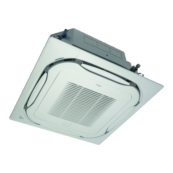
Summary of Contents for Daikin FXFQ20AVEB
- Page 1 INSTALLATION AND OPERATION MANUAL VRV System air conditioners System air conditioners FXFQ20AVEB FXFQ25AVEB FXFQ32AVEB FXFQ40AVEB FXFQ50AVEB FXFQ63AVEB FXFQ80AVEB FXFQ100AVEB FXFQ125AVEB...
- Page 2 ≥ ≥ 1500 ≥ ≥ 1500 1500 1500 860~910 ≤ 35 ≤ 35 ≤300 mm 1~1.5 m 5+10 70~90 mm...
- Page 3 3P290872-10E...
-
Page 4: Table Of Contents
SPECIFICALLY DESIGNED FOR USE WITH THE EQUIPMENT AND HAVE THEM INSTALLED BY A PROFESSIONAL. IF UNSURE OF INSTALLATION PROCEDURES OR USE, ALWAYS CONTACT YOUR DAIKIN DEALER FOR ADVICE AND INFORMATION. The English text is the original instruction. Other languages are translations of the original instructions. -
Page 5: Important Information Regarding The Refrigerant Used
Optional accessories For this unit you can select different air flow directions. It is necessary to purchase an optional blocking pad kit to discharge the air in 3 or ■ There are two types of remote controllers: wired and wireless. 4 (closed corners) directions. -
Page 6: Preparations Before Installation
Apply the long side of the NOTE Air flow directions as shown in figure 1 merely installation guide after removal serve as examples of possible air flow directions. of the tear-off tab in case of installation with self cleaning decoration panel Use suspension bolts for installation. -
Page 7: Indoor Unit Installation
■ To prevent water leakage, execute heat insulation work NDOOR UNIT INSTALLATION completely on both sides of the gas and liquid piping. When using a heat pump, the temperature of the gas piping can reach When installing optional accessories (except for the decoration up to approximately 120°C, use insulation which is sufficiently panel), read also the installation manual of the optional accessories. -
Page 8: Drain Piping Work
Piping insulation procedure RAIN PIPING WORK Gas piping Liquid piping Installation of drain piping Install the drain piping as shown in figure and take measures against condensation. Improperly rigged piping could lead to leaks and eventually wet furniture and belongings. 1-1.5 m Piping insulation material (field supply) Flare nut connection... -
Page 9: Electric Wiring Work
■ How to perform piping (See figure 7) Do not touch the drain pump. It may result in electric shock. Ceiling slab Control box lid Hanger bracket Power supply wiring Adjustable range Power supply terminal block Drain raising pipe (nominal diameter of vinyl pipe = 25 mm) Clamp (field supply) Drain hose (supplied with the unit) Unit transmission wiring... -
Page 10: Wiring Example And How To Set The Remote Controller
Electrical characteristics Precautions Observe the notes mentioned below when wiring to the power Model Volts Voltage range supply terminal block. min. 198-max. 264 / Use a round crimp-style terminal for insulation sleeve for FXFQ20~125 50 / 60 220-240 / 220 min. -
Page 11: Wiring Example
Summary of field settings IRING EXAMPLE Fit the power supply wiring of each unit with a switch and fuse as Mode First Second code No. (Note 2) shown in figure code (Note 1) No. Description of setting Filter contamination Power supply - Heavy/Light = Setting to define Main switch... -
Page 12: Test Operation
Control by 2 Remote Controllers (Controlling 1 indoor EST OPERATION unit by 2 remote controllers) Refer to the installation manual of the outdoor unit. When using 2 remote controllers, one must be set to "MAIN" and the other to "SUB". NOTE When performing field settings or test operation without attaching the decoration panel, do not touch... -
Page 13: Disposal Requirements
How to clean the air outlet and outside panels Open the suction grille (See figure 21) (action illustration). ■ Clean with a soft cloth. Push both levers simultaneously in the direction of the arrow as ■ indicated in the illustration and carefully lower the grille. When it is difficult to remove stains, use water or neutral (Identical procedure for closing.) detergent. -
Page 14: Wiring Diagram
IRING DIAGRAM Indoor unit Wired remote controller A1P,A2P ....Printed circuit board R1T...... Thermistor (air) C21,C105 .... Capacitor Receiver/display unit (attached to wireless remote controller) F1U ..... Fuse (T, 3, 15 A, 250 V) A3P,A4P ....Printed circuit board F2U ..... Field fuse BS1...... - Page 15 Control box Control box Control box IN/D OUT/D IN/D OUT/D OUT/D IN/D Control box IN/D OUT/D SETTING FORCED...
- Page 16 3P320142-1A 2012.10...


Need help?
Do you have a question about the FXFQ20AVEB and is the answer not in the manual?
Questions and answers