
Related Manuals for Daikin FXFQ20AVEB


Summary of Contents for Daikin FXFQ20AVEB
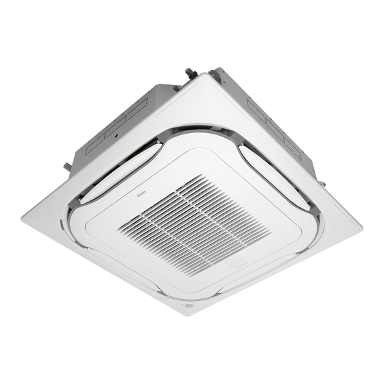
- Page 1 INSTALLATION AND OPERATION MANUAL System air conditioners FXFQ20AVEB FXFQ25AVEB FXFQ32AVEB FXFQ40AVEB FXFQ50AVEB FXFQ63AVEB FXFQ80AVEB FXFQ100AVEB FXFQ125AVEB...
- Page 2 3P290872-10...
- Page 3 ≥ ≥ 1500 ≥ ≥ 1500 1500 1500 60~910 ≤ 5 ≤ 5 ≤300 mm 1~1.5 m 5+10 70~90 mm...
-
Page 4: Table Of Contents
IF UNSURE OF INSTALLATION PROCEDURES OR USE, system and show him/her the enclosed operation manual. ALWAYS CONTACT YOUR DAIKIN DEALER FOR ADVICE AND INFORMATION. Explain to the customer what system is installed on the site. Be sure to fill out the appropriate installation specifications in the The English text is the original instruction. -
Page 5: Selecting Installation Site
(per speed setting Formula to calculate the greenhouse gas if applicable) emissions: GWP value of the refrigerant × Total refrigerant DAIKIN INDUSTRIES CZECH REPUBLIC s.r.o. Contact details U Nové Hospody 1/1155, 301 00 Plzeň charge [in kg] / 1000 Skvrňany, Czech Republic... -
Page 6: Preparations Before Installation
Use suspension bolts for installation. Check whether the ceiling is strong enough to support the weight of the indoor unit. If there is a risk, reinforce the ceiling before installing the unit. ≥1500 mm ≥1500 mm ≥2000 mm (The installation pitch is marked on the paper pattern for ≥4000 mm installation. -
Page 7: Indoor Unit Installation
Installation is possible when opening dimensions are as Fix the paper pattern for installation. (For new ceilings follows. only.) When installing the unit within the frame for fixing ceiling • The paper pattern for installation corresponds with the materials. (See figure 4) measurements of the ceiling opening. -
Page 8: Drain Piping Work
Be sure to use both a spanner and torque wrench together Gas piping Liquid piping when connecting or disconnecting pipes to/from the unit. Turn seams up Attach to base Torque wrench Tighten the part other than the piping insulation material Spanner Wrap over from the base of the unit to the top of the flare nut Piping union... - Page 9 NOTE The incline of attached drain hose should be 75 mm or less so that the drain socket does not have to withstand additional force. To ensure a downward slope of 1:100, install hanging bars every 1 to 1.5 m. When unifying multiple drain pipes, install the pipes as shown in figure...
-
Page 10: Electric Wiring Work
Electric wiring work NOTE For details, refer to "Wiring example" on page Allowable length of transmission wiring between General instructions indoor and outdoor units, and between the indoor unit and the remote controller is as follows: All field supplied parts and materials and electric works must conform to •... -
Page 11: Wiring Example
Keep total current of crossover wiring between indoor units less than Do not ground the equipment on gas pipes, water pipes, lightning rods 12 A. Branch the line outside the terminal block of the unit in or crossground with telephones. Improper grounding could result in accordance with electrical equipment standards, when using two power electric shock. -
Page 12: Test Operation
Mode First Second code No. (Note 2) Forced off on/off operation code input on → off: turns off the unit (Note 1) No. Description of setting Input "off" enables control (by remote controller) Setting for air outlet other ≤2.7 m >2.7 ≤3.0 m >3.0 ≤3.5 m —... -
Page 13: Disposal Requirements
How to clean the air filter NOTE When the suction grille is very dirty, use a typical Clean the air filter when the display shows " " (TIME TO kitchen cleaner and let it sit for about 10 minutes. CLEAN AIR FILTER). Then, wash it with water. -
Page 14: Unified Wiring Diagram Legend
Unified wiring diagram legend Unified Wiring Diagram Legend For applied parts and numbering refer to the wiring diagram sticker supplied on the unit. Part numbering is realized by Arabic numbers in ascending order for each part and is represented in the overview below by symbol “*” in the part code. CIRCUIT BREAKER CIRCUIT BREAKER PROTECTIVE EARTH... - Page 15 Control box Control box Control box IN/D OUT/D IN/D OUT/D OUT/D IN/D Control box IN/D OUT/D SETTING FORCED...
- Page 16 3P320142-1F 2017.08...
Need help?
Do you have a question about the FXFQ20AVEB and is the answer not in the manual?
Questions and answers