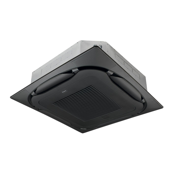
Daikin FXFQ20BVEB Installation And Operation Manual
Vrv system
Hide thumbs
Also See for FXFQ20BVEB:
- Installer and user reference manual (76 pages) ,
- Installation and operation manual (24 pages)
Subscribe to Our Youtube Channel
Summary of Contents for Daikin FXFQ20BVEB
- Page 1 Installation and operation manual VRV system air conditioner FXFQ20BVEB FXFQ25BVEB FXFQ32BVEB FXFQ40BVEB FXFQ50BVEB FXFQ63BVEB FXFQ80BVEB Installation and operation manual FXFQ100BVEB English VRV system air conditioner FXFQ125BVEB...
- Page 2 3P480520-14D...
-
Page 3: Table Of Contents
About the dry program ..........13 Daikin website (publicly accessible). 12.2.2 To use the dry program..........13 ▪ The full set of latest technical data is available on the Daikin 12.3 Adjusting the air flow direction........... 13 extranet (authentication required). -
Page 4: For The Installer
2 About the box For the installer About the box Indoor unit ≥1500 ≥2000 ≥4000 2.1.1 To remove the accessories from the indoor unit (mm) 1× 1× 1× 8× 4× 7× Minimum distance to the wall (see below) Minimum and maximum distance to the floor (see below) 20~63 class: ≥214 mm: In case of installation with standard decoration panel... -
Page 5: Installation
4 Installation Paper pattern for installation (upper part of the packing) Installation Screws (accessories) ▪ Ceiling opening and unit: Mounting the indoor unit ▪ Make sure the ceiling opening is within the following limits: Minimum: 860 mm to be able to fit the unit. 4.1.1 Guidelines when installing the indoor unit Maximum: 910 ... -
Page 6: Guidelines When Installing The Drain Piping
4 Installation Hanging bars (field supply) ▪ Level. Make sure the unit is level at all 4 corners using a level or a water-filled vinyl tube. ▪ Condensation. Take measures against condensation. Insulate the complete drain piping in the building. ▪... -
Page 7: Connecting The Refrigerant Piping
4 Installation ▪ Remove the switch box cover (a). 4.2.1 To connect the refrigerant piping to the ▪ Connect the user interface and transmission wiring (b). indoor unit ▪ Connect the power supply (1~ 220-240 V 50/60 Hz) and earth (c). CAUTION ▪... -
Page 8: Specifications Of Standard Wiring Components
4 Installation 5 Reattach the service cover. 4.3.1 Specifications of standard wiring components NOTICE When closing the service cover, make sure that the Component Class tightening torque for screws is ≤1.5N•m. 20~40 Wiring example Power 0.5 A 0.6 A 0.7 A 1.3 A 1.4 A supply cable For complete system example refer to the installer and user Voltage... -
Page 9: Configuration
5 Configuration Setting: Air volume when thermostat control is OFF Configuration This setting must correspond with the needs of the user. It determines the fan speed of the indoor unit during thermostat OFF Field settings condition. 1 If you have set the fan to operate, set the air volume speed: Make the following field settings so that they correspond with the actual installation setup and with the needs of the user: If you want... -
Page 10: Commissioning
6 Commissioning Action Commissioning Open the liquid stop valve (A) and gas stop valve (B) by removing the stem cap and turning NOTICE counterclockwise with a hex wrench until it stops. NEVER operate the unit without thermistors and/or pressure sensors/switches. Burning of the compressor might result. -
Page 11: Error Codes When Performing A Test Run
▪ A subset of the latest technical data is available on the regional Daikin website (publicly accessible). Error code Possible cause ▪ The full set of latest technical data is available on the Daikin Nothing displayed ▪ The wiring is disconnected or there is a extranet (authentication required). -
Page 12: For The User
9 About the system Pushbutton ON/OFF, operation Power module switch Switching power supply BZ, H*C Buzzer PTC* Thermistor PTC Capacitor Insulated gate bipolar transistor AC*, CN*, E*, HA*, HE*, HL*, Connection, connector (IGBT) HN*, HR*, MR*_A, MR*_B, S*, Q*DI Earth leak circuit breaker U, V, W, X*A, K*R_* Overload protector D*, V*D... -
Page 13: 11 Before Operation
11 Before operation Defrost operation Before operation In heating operation, freezing of the outdoor unit's air cooled coil increases over time, restricting the energy transfer to the outdoor WARNING unit's coil. Heating capability decreases and the system needs to go This unit contains electrical and hot parts. -
Page 14: About The Air Flow Flap
13 Maintenance and service 12.3.1 About the air flow flap Confirm setting. Circulation Air ow Save the settings? Double flow+multi-flow units Return Return Setting Setting For the following conditions, a micro computer controls the air flow direction which may be different from the display. Go to the home screen. -
Page 15: Cleaning The Air Filter, Suction Grille, Air Outlet And Outside Panels
13 Maintenance and service 13.2 Cleaning the air filter, suction grille, air outlet and outside panels CAUTION Turn off the unit before cleaning the air filter, suction grille, air outlet and outside panels. 13.2.1 To clean the air filter 4 Dry the air filter in the shadow. When to clean the air filter: 5 Reattach the air filter and close the suction grille. -
Page 16: To Clean The Air Outlet And Outside Panels
14 Troubleshooting NOTICE Applicable legislation on fluorinated greenhouse gases requires that the refrigerant charge of the unit is indicated both in weight and CO equivalent. Formula to calculate the quantity in CO2 equivalent tonnes: GWP value of the refrigerant × total refrigerant 4 Clean the suction grille. - Page 17 15 Disposal Disposal NOTICE Do NOT try to dismantle the system yourself: dismantling of the system, treatment of the refrigerant, oil and other parts MUST comply with applicable legislation. Units MUST be treated at a specialised treatment facility for reuse, recycling and recovery. FXFQ20~125BVEB Installation and operation manual VRV system air conditioner...
- Page 20 4P540926-1B 2019.01...


Need help?
Do you have a question about the FXFQ20BVEB and is the answer not in the manual?
Questions and answers