Advertisement
Table of Contents
- 1 Safety Considerations
- 2 Table of Contents
- 3 Before Installation
- 4 Selection of Installation Location
- 5 Preparation before Installation
- 6 Installation of Indoor Unit
- 7 Refrigerant Piping Work
- 8 Drain Piping Work
- 9 Electric Wiring Work
- 10 Mounting Decoration Panel
- 11 Field Setting and Test Operation
- Download this manual
See also:
Operating Manual
MODELS
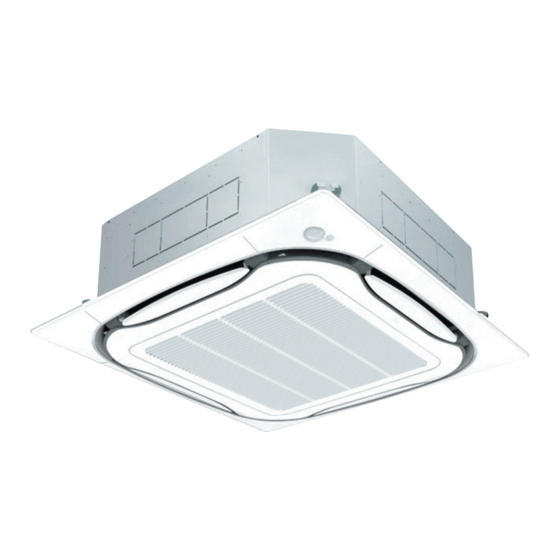
Ceiling Mounted Cassette type (Round Flow with Sensing Panel)
FXFQ07TVJU
FXFQ24TVJU
FXFQ09TVJU
FXFQ30TVJU
FXFQ12TVJU
FXFQ36TVJU
FXFQ15TVJU
FXFQ48TVJU
FXFQ18TVJU
READ THESE INSTRUCTIONS CAREFULLY BEFORE INSTALLATION.
KEEP THIS MANUAL IN A HANDY PLACE FOR FUTURE REFERENCE.
LIRE SOIGNEUSEMENT CES INSTRUCTIONS AVANT L'INSTALLATION.
CONSERVER CE MANUEL A PORTEE DE MAIN POUR REFERENCE ULTERIEURE.
LEA CUIDADOSAMENTE ESTAS INSTRUCCIONES ANTES DE INSTALAR.
GUARDE ESTE MANUAL EN UN LUGAR A MANO PARA LEER EN CASO DE TENER
ALGUNA DUDA.
3P161684-7N
INSTALLATION MANUAL
SYSTEM Inverter Air Conditioners
English
Français
Español
Advertisement
Table of Contents

Related Manuals for Daikin FXFQ24TVJU


Summary of Contents for Daikin FXFQ24TVJU
- Page 1 INSTALLATION MANUAL SYSTEM Inverter Air Conditioners MODELS English Ceiling Mounted Cassette type (Round Flow with Sensing Panel) FXFQ07TVJU FXFQ24TVJU FXFQ09TVJU FXFQ30TVJU FXFQ12TVJU FXFQ36TVJU Français FXFQ15TVJU FXFQ48TVJU FXFQ18TVJU Español READ THESE INSTRUCTIONS CAREFULLY BEFORE INSTALLATION. KEEP THIS MANUAL IN A HANDY PLACE FOR FUTURE REFERENCE.
-
Page 2: Safety Considerations
• Do not install unit in an area where flammable mate- other than those specified by Daikin are used, fire or rials are present due to risk of explosions that can explosion may occur. cause serious injury or death. - Page 3 • Do not touch the refrigerant pipes during and imme- (d) Where flammable gas may leak, where there is diately after operation as the refrigerant pipes may be carbon fiber, or ignitable dust suspension in the hot or cold, depending on the condition of the refriger- air, or where volatile flammables such as thinner ant flowing through the refrigerant piping, compres- or gasoline are handled. Operating the unit in such sor, and other refrigerant cycle parts.
-
Page 4: Table Of Contents
FXFQ07TVJU FXFQ24TVJU FXFQ09TVJU FXFQ30TVJU FXFQ12TVJU FXFQ36TVJU VRV SYSTEM Inverter Air Conditioners Installation Manual FXFQ15TVJU FXFQ48TVJU FXFQ18TVJU CONTENTS SAFETY CONSIDERATIONS .......[i] [ii] 1. BEFORE INSTALLATION .......... 2 2. SELECTION OF INSTALLATION LOCATION .... 3 3. PREPARATION BEFORE INSTALLATION ....5 4. INSTALLATION OF INDOOR UNIT ......5 5. -
Page 5: Before Installation
1. BEFORE INSTALLATION Name Sealing material When unpacking the indoor unit or moving the unit after Quantity 1 each 1 sheet 1 pc. unpacked, hold the hangers (4 places) and do not apply (10) Large force to other parts (particularly refrigerant piping, drain piping and resin parts). (12) Medium-2 • Make sure to check in advance that the refrigerant to be Shape used for installation work is R410A. -
Page 6: Selection Of Installation Location
CARRY OUT THE WORK GIVING CAUTION Points of the operation explanation TO THE FOLLOWING ITEMS AND AFTER THE In addition to the general usage, since the items in the WORK IS COMPLETED CHECK THESE AGAIN. operation manual with the WARNING and CAUTION marks are likely to result in human bodily injuries and property damages, it is neces sary Items to be checked after the installation work is... - Page 7 (2) Ceiling height (NOTE 1) • This indoor unit can be installed in a space of which Exhaust Indoor unit Indoor unit Lighting ceiling height is up to 11-1/2 ft. (3.5 m) (Type 30 · 36 · 48: 13-3/4 ft. (4.2 m)) *60 (1,500) 60 (1,500) or more...
-
Page 8: Preparation Before Installation
3. PREPARATION BEFORE INSTALLATION [unit: in. (mm)] Frame (1) Check the relation of location between the ceiling opening and the indoor unit hanging bolts. Refrigerant piping Ceiling material ≤1-3/8 (35) ≤1-3/8 (35) ≥13/16 ≥13/16 (20) (20) 33-7/8 to 35-7/8 (860 – 910) Hanging (Ceiling-opening dimension) (Ceiling-panel... - Page 9 (1) Install the indoor unit temporarily. (3) Adjust so that the unit will be properly positioned. • Fix the hanger to the hanging bolt. (Refer to 3. PREPARATION BEFORE INSTALLATION Make sure to securely fix the hanger with the nut and – (1)) the washer for hanger (3) from the upper and lower • Using the Installation guide (15) allows you to check...
-
Page 10: Refrigerant Piping Work
5. REFRIGERANT PIPING WORK Table 2 Piping Tightening Dimension for • For the outdoor unit refrigerant piping, refer to the installa- size torque processing flare Flare shape tion manual attached to the outdoor unit. [in. (mm)] [lbf·ft. (N·m)] A [in. (mm)] • Carry out insulation of both gas and liquid refrigerant piping 10.4 –... -
Page 11: Drain Piping Work
• Before brazing refrigerant piping, have nitrogen flow Gas side piping insulating method through the refrigerant piping and substitute air with nitrogen (NOTE 1) (Refer to Fig. 13). Then, carry out Joint insulating brazing (NOTE 2). material (8) (accessory) After all the brazing works are finished, carry out flare Flare nut Piping insulating connection with the indoor unit. - Page 12 <In case of sticking vinyl tape> 3–5 ft. (1–1.5 m) Tightened part Support Downward inclination of 1/100 or more Vinyl tape Good Stick vinyl tape without tearing the sealing material (Large) (10) . <In case of bending the tip> Wrong Tightened part Fig. 14 CAUTION...
- Page 13 CAUTION • Do not apply excessive force to the attached drain hose (1) by bending or twisting it. This could cause water leakage. • In case of centralized drain piping, carry out piping work according to the procedure shown in the fol lowing Fig. 18. Sealing material (14) (accessory) Fig. 20...
-
Page 14: Electric Wiring Work
FXFQ12TVJU 0.048 Fig. 22 FXFQ15TVJU 0.048 208/ Max. 253 FXFQ18TVJU 0.048 Min. 198 FXFQ24TVJU 0.048 FXFQ30TVJU 0.106 FXFQ36TVJU 0.106 FXFQ48TVJU 0.106 MCA: Min. Circuit Amps (A) MFA: Max. Fuse Amps (A) kW: Fan Motor Rated Output (kW) FLA: Full Load Amps (A) - Page 15 7-3 SPECIFICATION FOR FIELD SUPPLY FUSES • If a terminal is over tightened, it may be damaged. Refer to the table shown below for tightening torque of AND WIRING terminals. Remote controller wiring Tightening torque Power supply wiring Transmission wiring [lbf·ft.
- Page 16 • Use a 90° elbow type of conduit with dimensions Fig. 23-1 to prevent it from hitting the swing motor hous- ing of decoration panel. • Do not dispose the screw which assembles casing and resin together. The screw will be used to install conduit mounting plate.
- Page 17 1.When using 1 remote controller for 1 indoor unit. Wiring penetrating hole (Normal operation) Remote controller Outdoor unit Power supply Power supply Power supply Power supply wiring/transmission wiring single phase single phase single phase single phase Control box IN/D OUT/D 208/230 V 208/230 V 208/230 V 208/230 V 60 Hz 60 Hz 60 Hz...
-
Page 18: Mounting Decoration Panel
7-6 FOR CONTROL WITH 2 REMOTE CONTROL- Sheathed vinyl Wiring LERS (TO CONTROL 1 INDOOR UNIT WITH 2 cord or 2 core specification cable REMOTE CONTROLLERS) AWG18-16 • For control with 2 remote controllers, set one remote con- Gauge (0.75 – 1.25 mm troller as Main and the other remote controller as Sub. FORCED Max. -
Page 19: Field Setting And Test Operation
9. FIELD SETTING AND TEST OPERATION 9-3 SETTING WHEN AN OPTIONAL ACCESSORY IS ATTACHED <<Refer to also the installation manual attached to the • For setting when attaching an optional accessory, refer to outdoor unit.>> the installation manual attached to the optional accessory. CAUTION 9-4 WHEN USING WIRELESS REMOTE CONTROL- Before carrying out field setting, check the items mentioned in... - Page 20 < TEST OPERATION > • After cleaning the indoor unit inside, carry out test operation according to installation manual attached to the outdoor unit. • When the remote controller operation lamp flashes, it shows that something is abnormal. Check the malfunction codes on the remote controller. The relation between the malfunction codes and malfunction details is described in the operation manual attached to the outdoor unit.
Need help?
Do you have a question about the FXFQ24TVJU and is the answer not in the manual?
Questions and answers