Table of Contents
Advertisement
Advertisement
Table of Contents

Subscribe to Our Youtube Channel
Related Manuals for Daikin FXFQ-M


Summary of Contents for Daikin FXFQ-M
-
Page 1: Ceiling Mounted Cassette Type
EDUS 39 - 600 - F1_a FXFQ-M Ceiling Mounted Cassette Type (Multi Flow) AMERICAS... -
Page 2: Table Of Contents
EDUS39-600-F1_a FXFQ-M Ceiling Mounted Cassette Type (Multi Flow) 1. External Appearance...................2 2. Specifications ....................3 3. Dimensions ....................5 4. Piping Diagrams..................8 5. Wiring Diagrams..................9 6. Electric Characteristics................10 7. Capacity Tables ..................11 7.1 Cooling Capacity ..................11 7.2 Heating Capacity ..................12 8. -
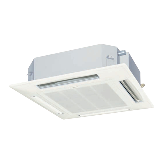
Page 3: External Appearance
External Appearance EDUS39-600-F1_a 1. External Appearance FXFQ12~36M FXFQ-M... -
Page 4: Specifications
3. Capacities are net, including a deduction for cooling (an addition for heating) for indoor fan motor heat. 4. Anechoic chamber conversion value, measured under JISB8616 conditions. During actual operation, these values are normally somewhat higher as a result of installation conditions. 5. Refer to page 10 for Power Input. FXFQ-M... - Page 5 3. Capacities are net, including a deduction for cooling (an addition for heating) for indoor fan motor heat. 4. Anechoic chamber conversion value, measured under JISB8616 conditions. During actual operation, these values are normally somewhat higher as a result of installation conditions. 5. Refer to page 10 for Power Input. FXFQ-M...
-
Page 6: Dimensions
EDUS39-600-F1_a Dimensions 3. Dimensions FXFQ12MVJU FXFQ18MVJU FXFQ-M... - Page 7 Dimensions EDUS39-600-F1_a FXFQ24MVJU FXFQ-M...
- Page 8 EDUS39-600-F1_a Dimensions FXFQ30MVJU FXFQ36MVJU FXFQ-M...
-
Page 9: Piping Diagrams
R1T : Thermistor for suction air temperature R2T : Thermistor for liquid line temperature R3T : Thermistor for gas line temperature Capacity Liquid φ1/2” (12.7 mm) φ1/4” (6.4 mm) 12/18 M φ5/8” (15.8 mm) φ3/8” (9.5 mm) 24/30/36 M FXFQ-M... -
Page 10: Wiring Diagrams
EDUS39-600-F1_a Wiring Diagrams 5. Wiring Diagrams FXFQ12M/18M/24M/30M/36MVJU FXFQ-M... -
Page 11: Electric Characteristics
Electric Characteristics EDUS39-600-F1_a 6. Electric Characteristics FXFQ-M... -
Page 12: Capacity Tables
EDUS39-600-F1_a Capacity Tables 7. Capacity Tables Cooling Capacity FXFQ-M Cooling capacity Indoor Air Temp. °FWB Outdoor air temp. Unit size °FDB 10.7 12.0 13.3 14.0 14.3 10.7 12.0 13.3 13.8 14.0 10.7 12.0 13.3 13.6 13.8 10.7 12.0 13.2 13.3 13.6... -
Page 13: Heating Capacity
Capacity Tables EDUS39-600-F1_a Heating Capacity FXFQ-M Heating Capacity Indoor Air Temp. °FDB Outdoor Air Temp. Indoor unit °FDB °FWB 22.0 20.0 11.7 11.7 11.6 11.6 11.6 11.6 26.0 24.0 12.2 12.2 12.2 12.2 12.2 12.1 30.0 28.0 12.8 12.8 12.7 12.7... -
Page 14: Air Velocity And Temperature Distributions
EDUS39-600-F1_a Air Velocity and Temperature Distributions 8. Air Velocity and Temperature Distributions FXFQ12M <Cooling mode> AIRFLOW DISTRIBUTIONS TEMPERATURE DISTRIBUTIONS FXFQ12M <Heating mode> AIRFLOW DISTRIBUTIONS TEMPERATURE DISTRIBUTIONS 3D052941 FXFQ-M... - Page 15 Air Velocity and Temperature Distributions EDUS39-600-F1_a FXFQ18M <Cooling mode> AIRFLOW DISTRIBUTIONS TEMPERATURE DISTRIBUTIONS FXFQ18M <Heating mode> AIRFLOW DISTRIBUTIONS TEMPERATURE DISTRIBUTIONS 3D052942 FXFQ-M...
- Page 16 EDUS39-600-F1_a Air Velocity and Temperature Distributions FXFQ24M <Cooling mode> AIRFLOW DISTRIBUTIONS TEMPERATURE DISTRIBUTIONS FXFQ24M <Heating mode> AIRFLOW DISTRIBUTIONS TEMPERATURE DISTRIBUTIONS 3D052943 FXFQ-M...
- Page 17 Air Velocity and Temperature Distributions EDUS39-600-F1_a FXFQ30M <Cooling mode> AIRFLOW DISTRIBUTIONS TEMPERATURE DISTRIBUTIONS FXFQ30M <Heating mode> AIRFLOW DISTRIBUTIONS TEMPERATURE DISTRIBUTIONS 3D052944 FXFQ-M...
- Page 18 EDUS39-600-F1_a Air Velocity and Temperature Distributions FXFQ36M <Cooling mode> AIRFLOW DISTRIBUTIONS TEMPERATURE DISTRIBUTIONS FXFQ36M <Heating mode> AIRFLOW DISTRIBUTIONS TEMPERATURE DISTRIBUTIONS 3D052945 FXFQ-M...
-
Page 19: Sound Levels
9. Sound Levels Overall Ceiling Mounted Cassette Type (Multi Flow) Notes: Operation noise differs with operation and ambient conditions. Model 208~230V, 60Hz FXFQ12MVJU FXFQ18MVJU FXFQ24MVJU FXFQ30MVJU FXFQ36MVJU Octave Band Level 208V~230V FXFQ12MVJU FXFQ18MVJU FXFQ24MVJU 4D052507 4D052508 4D052509 FXFQ30MVJU FXFQ36MVJU 4D052510 4D052511 FXFQ-M... -
Page 20: Installation
EDUS39-600-F1_a Installation 10. Installation Center of Gravity (inches) FXFQ12, 18, 24MVJU 9-1/8 4-1/2 FXFQ30, 36MVJU 11-3/8 6-3/4 4D042639A FXFQ-M... -
Page 21: Safety Considerations
Exposure to this gas can cause severe injury will cause injury. or death. FXFQ-M... - Page 22 Please instruct the cus- tomer to keep the area around the unit clean. NOTE • Install the indoor and outdoor units, power supply wir- ing, and connecting wires at least 3.5 ft. away from tele- FXFQ-M...
-
Page 23: Before Installation
Plastic parts may deteriorate and eventually cause the unit to fall out of place or leak. • Where sulfurous or other corrosive gas exists. Copper tubing and brazed spots may corrode and lead to refrigerant leaks. FXFQ-M... - Page 24 Table 1 Optional decoration panel Model Color White FXFQ12 · 18 · 24 · 30 · 36MVJU BYC125KW1 Table 2 Remote controller Wired type BRC1D71 FXFQ-M...
-
Page 25: Selecting Installation Site
Number of discharge outlets used Model FXFQ30M·36M FXFQ12 · 18 · 24MVJU 9 7/16 or more 4-way air 3-way air 2-way air FXFQ30 · 36MVJU 11 3/4 or more discharge discharge discharge Ceiling (length: in.) Standard 10.5 11.8 13.8 height FXFQ-M... -
Page 26: Preparations Before Installation
Adjust clearance from the ceiling before proceeding further. 〈 Installation example 〉 33 1/16 Ceiling slap 35 13/16 Anchor Long nut or turn-buckle Dimension inside frame) Suspension bolt False ceiling NOTE) All the above parts are field supplied. FXFQ-M... -
Page 27: Indoor Unit Installation
Inner insulation Side plate Edge Insulation Approx. 3/8” Make sure the inner surface of insulation tightly contacts with the inner insulation edge and the side plate. Fig. 2 FXFQ-M... -
Page 28: Refrigerant Piping Work
(5) Remove the paper pattern for installation (5). Spanner Piping union Flare nut Water level Vinyl tube For existing ceilings (6) Adjust the height and position of the unit. Refer toPREPARATIONS BEFORE INSTALLATION-(1). (7) Perform steps (4), (5) in “6-1 For new ceilings”. FXFQ-M... - Page 29 • Check the pipe connector for gas leaks, then insulate it as does not require flux. shown in the following drawing. (Flux has an extremely negative effect on refrigerant piping systems. For instance, if chlorine based flux is used, it will cause pipe corrosion and damage the refrigerant oil. FXFQ-M...
-
Page 30: Drain Piping Work
Metal clamp 2) Large sealing pad 10) WHEN ELECTRIC WIRING WORK IS FINISHED (attached) (attached) • Check drainage flow during COOL running, explained under TEST OPERATION. 3/16” or less NOTE FOR DRAIN RAISING PIPING FXFQ-M... -
Page 31: Electric Wiring Work
Allowable length of transmission wirings and remote controller wiring are as follows. (1) Outdoor unit – Indoor unit: Max. 3280 ft. / 1000 m (Total wiring length: 6560 ft. / 2000 m) (2) Indoor unit – Remote controller: Max. 1640 ft. / 500 m FXFQ-M... - Page 32 (6P) Electric parts box lid (1) diagram label Electric parts box lid (2) Round crimp-style terminal Clamp A Electric wire Connect wires of the same gauge to Clip both sides. L1 L2 Power supply Power supply terminal block (3P) FXFQ-M...
- Page 33 Remote controller PC board Only one remote controller needs to be Indoor unit A Indoor unit B Indoor unit C changed if factory Most downstream settings have remained indoor unit untouched. Remote Remote Remote Remote controller controller controller controller FXFQ-M...
- Page 34 Approx. 1250 hrs OFF OPERATIONS in response to Input A. The T1-T2 heavy terminals are standard on all Daikin indoor units and When using wireless remote controllers allow for remote starting and stopping of equipment. • When using wireless remote controllers, address setting is Individual indoor units can be field prgrammed at the necessary.
-
Page 35: Field Setting
/ or the FORCED OFF wiring. PANEL Refer to the installation manual attached to the decoration panel. After installing the decoration panel, ensure that there is no space between the unit body and decoration panel. FXFQ-M... -
Page 36: Accessories
Filter chamber for KDDFP55D160 related above Ultra-long life filter KAFP55D160 Long life Non- replacement woven KAFJ551K160 filter type Fresh air intake kit KDDJ55X160 Panel spacer KDBP55H160WA C : 3D043021 Optional Assessories for Controls can be found in the Controller Manual. FXFQ-M... - Page 37 Accessories EDUS39-600-F1_a FXFQ-M...
- Page 38 AMERICAS 1645 Wallace Drive, Suite 110 Carrollton, TX75006 info@daikinac.com www.daikinac.com Aug. 2009 EDUS39-600-F1_a Printed in U.S.A. 08/2009...
Need help?
Do you have a question about the FXFQ-M and is the answer not in the manual?
Questions and answers