Table of Contents
Advertisement
Quick Links
Advertisement
Table of Contents

Subscribe to Our Youtube Channel
Related Manuals for AnyTone NSTIG-8R


Summary of Contents for AnyTone NSTIG-8R
- Page 1 Package and Product Designed in U.S.A. MADE IN CHINA AnyToneTech.com Copyright © 2015 by AnyTone Tech All rights reserved. No part of this publication may be reproduced, distributed, or transmitted in any form or by any means without the permission of AnyTone Tech...
- Page 2 USER'S MANUAL...
- Page 3 FM radio, and many more features. This radio is a meticulously built and a functional hand-held intended for every radio operator. MODELS APPLY TO THIS MANUAL NSTIG-8R FM Transceiver Programming software: NSTIG-8R USB PROGRAMMING PRECAUTION When programming the transceiver, first read from the radio, before modifying the frequencies data and...
- Page 4 WARNINGS transceivers are intelligently designed with advanced technologies. The following tips are required to prevent voiding warranty and understanding the safety of transceiver usage. 1.Keep the transceiver and all accessories away from children. 2.Do not try to open or modify the transceiver without permission. Irresponsible operation of the transceiver may also cause damage.
-
Page 5: Table Of Contents
CONTENTS UNPACKING ........................................01 Supplied Accessories ....................................01 STANDARD ACCESSORIES/ADDITIONAL ACCESSORIES ....................02 Standard Accessories ....................................02 Additional Accessories ....................................02 USER MODE SETUP:AMATEUR OR COMMERCIAL RADIO ..................... 03 BATTERY INFORMATION ..................................05 Charging Operation ....................................05 Battery Charger Type .................................... - Page 6 CONTENTS Frequency Adjusting ....................................15 FM Channel Searching ....................................16 Receiving ........................................16 Transmitting ........................................17 Emergency Alarm .......................................17 Keypad reference chart ....................................18 Side Key [PF1]/[PF2] function instruction ............................21 MONI Key Function ....................................21 Add a channel ......................................22 Delete a channel ......................................22 Limit VFO frequency scanning range ..............................
- Page 7 CONTENTS CTCSS/DCS Encode/Decode Synchronous Setup ........................32 Optional signaling setup ...................................33 Squelch mode setup ....................................33 Frequency step size setup ..................................34 Wide / Narrow Band Selection ................................35 Frequency Reverse ....................................35 Talk Around ON/OFF ....................................36 Offset Frequency setup .....................................36 Editing Channel name ....................................37 Busy Channel Lockout ....................................37 TX OFF...
- Page 8 ATTACHED CHART .....................................66 CTCSS Frequency Chart ..................................66 1024 groups DCS frequency chart ...............................67 FCC COMPLIANCE .....................................70 Usage of Your Transceiver on Part 90 (Commercial) and Part 97 (Amateur) Frequencies ..........70 LIMITED WARRANTY (UNITED STATES) ............................71 ANYTONE TECH’S LETTER TO YOU ...............................72...
-
Page 9: Unpacking
UNPACKING Carefully unpack the transceiver. We recommend that you identify the items listed in the following table before discarding the packaging. If any items are missing or have been damaged during shipment, please contact your dealer immediately. Supplied Accessories Item Number Quantity Antenna... -
Page 10: Standard Accessories/Additional Accessories
*1.Note: For frequency band of antenna, please refer to label indicated in the bottom of the antenna. Belt Clip Instruction Manual BC06 Additional Accessories USB Programming Programming Software Handheld Microphone Battery Pack for Car Cable Charger QHM22 NSTIG-8R PC03 Telescopic antenna Li-ion Battery QA10UV 1300mAh... -
Page 11: User Mode Setup:amateur Or Commercial Radio
USER MODE SETUP:AMATEUR OR COMMERCIAL RADIO The transceiver is a high performance amateur and professional radio with dual band, dual standby, dual display and other advanced features. According to your specific application, you can set the radio to operate as an Amateur Transceiver or as a Professional (Commercial) Transceiver. There are 3 operating modes - and you can pick the mode best suited for your needs at anytime. - Page 12 USER MODE SETUP:AMATEUR OR COMMERCIAL RADIO "NAME", it enters into Name Tag + Channel Mode. In this mode, it will display the corresponding channel name (if you have given a Channel name in the memory). If no name is given, it will display the frequency + channel number.
-
Page 13: Battery Information
BATTERY INFORMATION Charging Operation The battery is not charged at the factory, please charge it before your initial use. Charging the battery for the first time or charging it after extended storage (more than 2 months) may not bring the battery to its maximum operating capacity after the first charge.It may take repeating a full charge/discharge cycle for two or three times before the operating capacity reaches its maximum performance. -
Page 14: How To Charge
BATTERY INFORMATION damage the battery. ▲ Do not charge the battery or transceiver if it is damp or wet. Dry it before charging to avoid any danger. WARNING: When keys, ornamental chains, or other metals contact or short the battery terminals, the battery could cause a shock or injury. - Page 15 BATTERY INFORMATION NOTE: When charging a powered on transceiver equipped with battery, the LED will not turn to green to show the full charge status. Only when you turn off the transceiver, will the LED indicate normally. If the transceiver is powered on, it will continually consume energy.
-
Page 16: Charging Prompts Explained
BATTERY INFORMATION Charging Prompts Explained Self- examination: When plugging in your charger, the ORANGE light may flash for 1 second and go out. This means that the charger has passed its self-examination and it can charge the battery normally. If the light remains orange or the red light flashes this means the charger cannot pass its self- examination test and it will not charge the battery. -
Page 17: Preparation
PREPARATION Installing / Removing the Battery ■ Installing the Battery Lay the battery to face the back of the radio. Press the bottom of the battery, the latch in the bottom of the transceiver lock will release. After hearing a "click", the battery has been locked. -
Page 18: Installing / Removing The Belt Clip
PREPARATION Installing / Removing the Belt Clip ■ Installing the Belt Clip: Place the belt clip to the grooves on the back of the transceiver, and then install the screws, turning clockwise. ■ Removing the Belt Clip: Remove the screws turning counterclockwise, allowing you to remove the belt clip. -
Page 19: Getting Acquainted
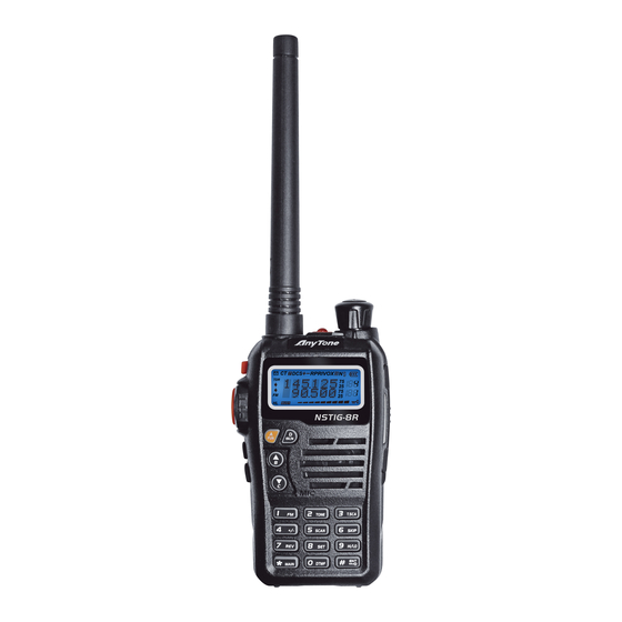
GETTING ACQUAINTED LCD Display On the LCD display screen, you will see various icons appear which stand for the functions you may have enabled. In order to thoroughly understand the icons and their meanings an overview is provided below: Frequency VOX Function Reverse Offset Frequency... - Page 20 GETTING ACQUAINTED NSTIG-8R ESC/M...
- Page 21 GETTING ACQUAINTED Antenna Lamp (Flashlight) Power / Volume Switch Rotate it clockwise to turn on the transceiver, rotate it counterclockwise until you hear the "click" to turn off the transceiver. When the transceiver is powered on, turn the knob clockwise to increase volume, or turn the knob counterclockwise to reduce the volume.
-
Page 22: Basic Operations
BASIC OPERATIONS Turn the Radio On & OFF When the radio is off, turn the [POWER]/[VOLUME] knob clockwise to turn on the transceiver. The transceiver will play a prompt tone and displays the current channel on screen once it has fully powered on. When the radio is on, turn the [POWER]/[VOLUME] knob counterclockwise until you hear a "Click". -
Page 23: Channel Adjusting
BASIC OPERATIONS NOTE: When the transceiver is in channel mode the right side of the frequency will display the channel number. Channel Adjusting 1. Input channel number by scrolling When the transceiver is in Channel mode or in the FM radio channel mode, press to go through the channels. -
Page 24: Fm Channel Searching
BASIC OPERATIONS 1. Enter the desired frequency by increments. Press to increase by frequency step, Press to decrease frequency step. Every button press will add or reduce the frequency by one stepping value. NOTE: Channel step increments:2.5K, 5K, 6.25K, 10K, 12.5K, 20K, 25K, 30K and 50KHz. The FM radio step increment is 50K. -
Page 25: Transmitting
BASIC OPERATIONS NOTE: You may not receive the call if your transceiver is set at a high squelch level. If the current channel is programmed with a mandatory decode (RX) tone (CTCSS, DCS, etc), the selected tone also must be present for the call to be heard. -
Page 26: Keypad Reference Chart
BASIC OPERATIONS Keypad reference chart When Pressed The Key is Entering a Frequency Inputting an Alpha When Pressed The Key is Pressed and or Recalling a Memory Tag Inputting CTCSS and Held over Pressed after held when Channel (Or FM Mode) / DCS Tone 1 second "A"... - Page 27 BASIC OPERATIONS Enable / Disable: CTCSS / DCS Tone Number "3" Scan (on active selected tone mode) Cloning Cable Alpha Tag: Previous Enable / Disable: Number "4" See Explanation Character Offset Direction in Guide Enable Scan Number "5" Enable / Disable: Number "6"...
- Page 28 BASIC OPERATIONS Programmed PF 1 Function Exit Menu PTT (if TX is enabled) FM Mode: Listen to FM in Exit Menu Background Programmed PF 2 Function Exit Menu Enters Advanced Programmed MONI Function Mode [MONI] (Monitor) Function Exit Menu See Explanation See Explanation in Guide in Guide...
-
Page 29: Side Key [Pf1]/[Pf2] Function Instruction
BASIC OPERATIONS Side Key [PF1]/[PF2] function instruction VOLT: Battery capacity inquiry: Under standby, press [PF1]/[PF2] key, the LCD displays the current battery capacity, press the key again to exit. CALL: Transmit the pre-stored DTMF Encode signal ALARM: Activated by a long press of the [PF1]/[PF2] key. The LCD will display "ALARM" and the transceiver will enable the preset alarm function. -
Page 30: Add A Channel
BASIC OPERATIONS Add a channel Under frequency mode (VFO), after you have set up your desired frequency and settings (read through the Function Menu Setup in order to understand how to set your desired frequency settings), Press key, the top left corner of LCD will display the " "... -
Page 31: Turn On/ Off Fm Radio
BASIC OPERATIONS on the same frequency band. L2 and U2 must also be used on the same frequency band, When the VFO frequency is between L1 and U1 or L2 and U2, the radio will scan between them when scanning is activated. -
Page 32: Ctcss/Dcs Setup
BASIC OPERATIONS radio frequency, The FM radio is now on. When the FM radio is on, press key, LCD displays "FM OFF",The FM radio is now muted. When FM radio is on, press key, the top left corner of LCD displays " "... -
Page 33: Offset Frequency Direction Setup
BASIC OPERATIONS key to enter into CTCSS/DCS scan. Under this state, press change the scanning direction. When the scan receives CTCSS/DCS signaling, it will stay 5seconds and then continue scanning. Press any other keys except , key to exit. NOTE: This function is will not work when the transceiver is set up in professional mode or the current selected channel does not have any CTCSS/DCS signal first set up. -
Page 34: Frequency/Channel Scan
BASIC OPERATIONS Frequency/Channel Scan Under the corresponding mode, press key, the top left corner of the LCD will display " " icon, then press key to start frequency scan or channel scan. 1. Frequency Scan Under VFO mode, frequency scanning is available. The frequencies will be scanned by the transceiver's ‘step’... -
Page 35: Channel Scan Skip
BASIC OPERATIONS Channel Scan Skip Under channel mode, press key, the top left corner of LCD displays " " icon, then press to set the current selected channel as Channel scan skip.Repeat above operation to cancel channel scan skip. LCD displayed "... -
Page 36: Dtmf Code Transmit And Enquiry
BASIC OPERATIONS When LCD displays " L" icon, it means low power has been chosen. When LCD displays " H" icon, it means high power has been chosen. DTMF code Transmit and Enquiry Press key, the top left corner of the LCD will display " "... -
Page 37: Keypad Lock
BASIC OPERATIONS Keypad lock In order to prevent accidental operation, the user can make use of the keypad lock function. When in standby, press key, the top left corner of the LCD will display " " icon, then press and hold key until you hear a responsive beep and the LCD displays "... -
Page 38: Function Menu Setup
FUNCTION MENU SETUP Menu 1-13 of this transceiver are channel operations. Channel operations will temporarily change the functions of the current channel. When the power is off or the channel has been changed, the relevant setup will be erased. Only under VFO mode, will the channel operations will be saved until your next change. Menu 14-32 are background operations, and they are valid for all channels, the relevant setup will be saved until next change. -
Page 39: Ctcss/Dcs Decode Setup
FUNCTION MENU SETUP CTCSS: 62.5Hz-254.1Hz, 51groups in total, and 1 group user-defined code. DCS: 000N-777I, 1024 groups in total. "N" stands for positive code, "I" stands for inverse code. Note: User-defined CTCSS encode must be setup by programming software. CTCSS/DCS Decode Setup If this function is enabled, you can ignore (can not hear) other unrelated call on the same frequency. -
Page 40: Ctcss/Dcs Encode/Decode Synchronous Setup
FUNCTION MENU SETUP CTCSS/DCS Encode / Decode Synchronous Setup This function is for adjusting CTCSS/DCS encode/decode as a synchronous set up (simultaneous changes Menu NO 01 and 02) Press key, the top left corner of the LCD will display " "... -
Page 41: Optional Signaling Setup
FUNCTION MENU SETUP Optional signaling setup DTMF is similar to CTCSS/DCS, it has a special call functions, such as ANI, PTT ID, All call, Alarm, remotely kill, remotely stun and remotely waken, etc.. Press key, the top left corner of the LCD will display " "... -
Page 42: Frequency Step Size Setup
FUNCTION MENU SETUP SQ: When current channel received matching RF signals, transceiver can hear the talking from the other party. CT/DCS: When current channel received matching RF signals and matching CTCSS/ DCS signaling, transceiver can hear the talking from the other party. TONE: When current channel received matching RF signals and matching optional signaling, transceiver can hear the talking from the other party. -
Page 43: Wide / Narrow Band Selection
FUNCTION MENU SETUP NOTE: This function item will hide automatically when main band and sub main band are under channel mode. Wide / Narrow Band Selection According to the laws of various countries on frequency spectrum, you can set communication for (25k) wide band or (12.5k) narrow band. Press key, the top left corner of the LCD will display "... -
Page 44: Talk Around On/Off
FUNCTION MENU SETUP ON: This will turn on the Frequency reverse function, TX and RX frequency of the current channel will be switched. If there is a CTCSS/DCS signaling set, they will also be interchanged. OFF: This will turn off Frequency reverse function. 4. -
Page 45: Editing Channel Name
FUNCTION MENU SETUP 1. Press key, the top left corner of the LCD will display " " icon, then press key to enter into function menu. 2. Press key to choose NO. 10 function item, it shows "OFFSET" on LCD. 3. -
Page 46: Tx Off
FUNCTION MENU SETUP 1. Press key, the top left corner of the LCD will display " " icon, then press key to enter into function menu. 2. Press key to choose NO. 12 function item, it shows "RPLOCK" on LCD. 3. -
Page 47: Single Band Mode (Vhf/Uhf)
FUNCTION MENU SETUP Single Band Mode (VHF/UHF) When this function is on, the input frequency and scanning of frequencies under VFO is limited to the current active VFO frequency band (VHF or UHF). 1. Press key, the top left corner of the LCD will display " "... -
Page 48: Keypad Voice Prompt Setup
FUNCTION MENU SETUP Keypad Voice Prompt Setup 1. Press key, the top left corner of the LCD will display " " icon, then press key to enter into function menu. 2. Press key to choose NO. 16 function item, it shows "BEEP" on LCD. 3. -
Page 49: Voice Operated Transmission (Vox) Setup
FUNCTION MENU SETUP Voice Operated Transmission (VOX) Setup When this function is enabled, the transmitting can be started by your voice (generally used with an ear- piece), When it is enabled there is no need to press the [PTT] key. 1. -
Page 50: Automatic Power Off Time Setup
FUNCTION MENU SETUP Automatic Power Off Time setup When this function is on, transceiver will automatically power off after it reaches the preset time allowance. 1. Press key, the top left corner of the LCD will display " " icon, then press key to enter into function menu. -
Page 51: Squelch Level Setup
FUNCTION MENU SETUP Squelch level setup This function is used to setup open the squelch of receiving signals, the transceiver will only allow calls when the receiving signal strength hits a minimum strength clarity, otherwise, the transceiver will remain muted. 1. -
Page 52: Function Icon Stay Time Setup
FUNCTION MENU SETUP 2SP: When scanning matched signal, transceiver will stop scanning, 2 seconds after the signal has completed it will resume scanning. 4. Press key or key to confirm and exit. Function Icon Stay Time Setup 1. Press key, the top left corner of the LCD will display " "... -
Page 53: Lcd Backlight Setup
FUNCTION MENU SETUP NOTE: When the function icon is set to stay, the user can set the desired functions continuously, without a need to press the function key every time. LCD Backlight Setup 1. Press key, the top left corner of the LCD will display " "... -
Page 54: Self Id Inquiry
FUNCTION MENU SETUP BLUE: Blue backlight ORG: Orange backlight PUR: Purple backlight 4. Press key or key to confirm and exit. Self ID inquiry 1. Press key, the top left corner of the LCD will display " " icon, then press key to enter into function menu. -
Page 55: Battery Save Setup
FUNCTION MENU SETUP 1750HZ, 2100HZ, 1450HZ, 1000HZ - These are the 4 settings you can set as required by your local repeater. 4. Press key or key to confirm and exit. Battery Save Setup You can set a battery save ratio according to your requirements. The standby time can be extended if you enable the battery save function, but if you set the ratio setting too high, it may cause you to miss the beginning of a transmission. -
Page 56: Fm Radio
FUNCTION MENU SETUP FM radio 1. Press key, the top left corner of the LCD will display " " icon, then press key to enter into function menu. 2. Press key to choose NO. 30 function item, it shows "RADIO" on LCD. 3. -
Page 57: Pf2 Key Function Setup
FUNCTION MENU SETUP ALARM: Emergency call function. SUBPTT: Sub band PTT. LAMP: Flashlight. OFF: No function. 4. Press key or key to confirm and exit. PF2 key Function Setup You, can program the PF2 key to best suit your requirements. 1. -
Page 58: Function Menu Quick Reference
FUNCTION MENU SETUP Menu Description LCD Display Function Options No CTCSS/DCS Encode CTCSS/DCS 51 groups fixed CTCSS encode+1 group self- T-CDC 62.5HZ-254.1Hz+Self defined defined CTCSS encode Encode 1024 groups DCS Encode 000N-777I No CTCSS/DCS Decode CTCSS/DCS 51 groups fixed CTCSS decode+1 group self- R-CDC 62.5HZ-254.1Hz+Self defined defined CTCSS decode... - Page 59 FUNCTION MENU SETUP When current channel received matching RF signals + matching optional signaling + matching CTCSS/ CT&TO DCS signaling, transceiver can hear the Squelch mode talking from the other party. SIGNAL setup When current channel received matching RF signals, or matching optional signaling, or matching CT/TO CTCSS/DCS signaling, transceiver can hear the talking from the other party.
- Page 60 FUNCTION MENU SETUP Carrier wave lock, transmitting is prohibited when BUSY received matching carrier wave. Busy Channel Signaling lock, transmitting is prohibited when RPLOCK Lockout REPEAT received matching carrier but with mismatching CTCSS/DCS Close B CLO function. TX function is enabled in current channel TX OFF TX function is disabled in current channel Single Band Mode...
- Page 61 FUNCTION MENU SETUP Disable the Automatic power off function Automatic Power Off Setup 30MIN-2HOUR 30minutes ~ 2hours: Total 3 levels for optional DTMF DTMF 50MS-500MS Total 5 kinds of DTMF transmitting time for optional Transmitting Time Squelch level 10 levels of squelch in total for optional, "00" is minimum 00-09 setup value (normally open) Setup...
- Page 62 FUNCTION MENU SETUP Tone Pulse 1750Hz/2100Hz/1450Hz/ Tone plus frequency is 1750Hz/2100HZ/1450Hz TBST Frequency 1000Hz /1000Hz Selection Turn off battery save function. Battery Save SAVE 1:2-1:8 Battery save time is 1:2-1:8 Setup AUTO Battery save ratio is adjusting automatically. RADIO FM radio ON/OFF Allow/Prohibit using FM radio.
-
Page 63: Advanced Function Operations
ADVANCED FUNCTION OPERATIONS Programming a Duplex Channel Example This example is for: 146.700MHz 600kHz minus offset into channel 99 CTCSS tone 123.0 (optional). 1. Set radio to VFO Mode (Frequency Mode) a.) Press button switch VFO/MR 2. Select Display A (select the Upper Display) a.) Press button and select the Upper Display. -
Page 64: Display Mode Setup
ADVANCED FUNCTION OPERATIONS a.) Press button and then press button b.) Press button select Menu 03 c.) Press button d.) Press button to choose CTCSS, DCS or OFF, when DCS signaling is selected, press button to choose DCS positive or inverse code e.) Press button select 123.0HZ,when CTCSS display 88.5HZ(default ) f.) Press... -
Page 65: Resume Factory Default
ADVANCED FUNCTION OPERATIONS 3. Press enter into next menu, then press to select desired setting. FREQ: Frequency + Channel mode, transceiver displays current channel number + frequency, press key to switch into VFO mode. CH: Channel mode (for commercial use), 1~21 items of function menu will be disabled, the user can only operate some functions. -
Page 66: Optional Signaling (Dtmf)
ADVANCED FUNCTION OPERATIONS INIT: Resume background settings to factory default, channel operations are keeping. 4. Press key to exit current selection. 5. Press key to confirm current selection. Note: In power off state, hold key to power on radio, the radio will resume to factory default. - Page 67 ADVANCED FUNCTION OPERATIONS Radio A Radio B Radio C Radio D ID Code If the calling party uses "C23" to call, Radio A and Radio B will receive the call. If the calling party uses"CC5" to call, Radio C and Radio D will receive the call. If the calling party uses "CCC"...
-
Page 68: Cloning Cable
This feature will copy the programmed data and parameters from the master unit to slave units. It copies the parameters and memory program settings. Connection: Use optional CP04 cloning cable, connect NSTIG-8R NSTIG-8R Read / write frequency port on both master and slave, ESC/M ESC/M setting and programing as the requirement below. - Page 69 ADVANCED FUNCTION OPERATIONS [Settings: Slave side] 1. In the standby mode, when the slave receives the data, the display shows "CLONE XX" XX stands for the data being cloned. 2. When data reception is complete, the slave unit returns to normal mode and restarts automatically.
-
Page 70: Programming Software Starting(Uses The Windows Operating System)
2.Please plug the programming cable into the USB port of the PC device,then connect to transceiver. (A Genuine FTDI cable from is recommended) 3.Double click "NSTIG-8R" shortcut icon, or click NSTIG-8R item in "START" menu to open programming software interface. 4.Choose your "COM Port", then click "OK" to start programming software. -
Page 71: Technical Specification
TECHNICAL SPECIFICATION General Receiving Part VHF: 136~174MHz Wide band narrow band Frequency Range UHF: 400~480MHz Sensitivity ( EX: 400~520MHz) ≤0.25μV ≤0.35μV (12dB SInAD) Channel Capacity 200 channels Adjacent Channel 25KHz (wide band) ≥65dB ≥60dB Channel Spacing Selecitvity 12.5KHz (narrow band) Intermodulation ≥60dB ≥60dB... -
Page 72: Trouble Shooting Guide
TROUBLE SHOOTING GUIDE Problem Corrective Action A.The battery may be depleted. Recharge or replace the battery. B.The battery may not be installed correctly. Remove the battery and install it again. No power C.The power switch is broken; Contact local dealer for repair. D.Battery tabs or the connection is broken;... - Page 73 TROUBLE SHOOTING GUIDE Can not power on or frequent Check if the battery is making good contact and is locked in place. power off The transmitting audio gets low Check if the MIC hole is plugged. If you cannot diagnose the issue or intermittent -contact local dealer for repair.
-
Page 74: Attached Chart
ATTACHED CHART CTCSS Frequency Chart 62.5 94.8 136.5 177.3 218.1 67.0 97.4 141.3 179.9 225.7 69.3 100.0 146.2 183.5 229.1 71.9 103.5 151.4 186.2 233.6 74.4 107.2 156.7 189.9 241.8 77.0 110.9 159.8 192.8 250.3 79.7 114.8 162.2 196.6 254.1 82.5 118.8 165.5... -
Page 75: 1024 Groups Dcs Frequency Chart
ATTACHED CHART 1024 groups DCS frequency chart... - Page 76 ATTACHED CHART...
- Page 77 ATTACHED CHART NOTE: N stands for positive code. I stands for inverted code. 1024 groups of DCS in total.
-
Page 78: Fcc Compliance
FCC COMPLIANCE Usage of Your Transceiver on Part 90 (Commercial) and Part 97 (Amateur) Frequencies Changes or modifications to this device not expressly approved by ANYTONE could void the user's authorization to operate this device. This device complies with part 90 of the FCC Rules. Operation is subject to the following two conditions:(1)This device may not cause harmful interference, and (2) this device must accept any interference including received, interference that may cause undesired operation. -
Page 79: Limited Warranty (United States)
LIMITED WARRANTY (UNITED STATES) You MUST file your warranty information online at: AnyToneTech.com within 45 days of purchase. will repair or replace, at its option without charge, subject to the exclusions set forth below, any Two-Way -Radio transceiver which fails due to a defect in material or workmanship within ONE year following the initial consumer purchase. -
Page 80: Anytone Tech's Letter To You
ANYTONE TECH’S LETTER TO YOU: specializes in communication equipment, but even more important than communication with others - is your communication with God. To become a Christian and receive salvation is the greatest step you can take with God. To be real it must be a personal commitment from the heart.
Need help?
Do you have a question about the NSTIG-8R and is the answer not in the manual?
Questions and answers