Table of Contents
Advertisement
Quick Links
Advertisement
Table of Contents

Related Manuals for AnyTone ANILE-8R


Summary of Contents for AnyTone ANILE-8R
- Page 1 Package and Product Designed in U.S.A. MADE IN CHINA AnyToneTech.com Copyright © 2015 by AnyTone Tech All rights reserved. No part of this publication may be reproduced, distributed, or transmitted in any form or by any means without the permission of AnyTone Tech...
- Page 2 USER'S MANUAL...
- Page 4 DTMF encode/decode, programmable shortcut keys, and many more features. This radio is a meticulously built and a functional hand-held intended for every radio operator. MODELS APPLY TO THIS MANUAL User Manual Applied to: ANILE-8R UHF FM Transceiver VHF FM Transceiver Programming Software: ANILE-8R...
- Page 5 CAUTIONS transceivers are intelligently designed with advanced technologies. The following tips are required to prevent voiding warranty and understanding the safety of transceiver usage. Keep the transceiver and all accessories away from children. Do not try to open or modify the transceiver without permission. Irresponsible operation of the transceiver may also cause damage.
-
Page 6: Table Of Contents
CONTENTS UNPACKING ............................1 Supplied Accessories ..............................2 STANDARD ACCESSORIES/OPTIONAL ACCESSORIES ..............2 Standard Accessories ..............................2 Optional Accessories ..............................2 BATTERY INFORMATION ........................3 Charging Operation ..............................3 Battery Charger Type ..............................3 Notice for Charging Battery ............................3 How to Charge ................................4 Charging Prompts Explained .............................5 How to Store the Battery ............................6 PREPARATION .............................7 Installing / Removing the Battery ..........................7... - Page 7 CONTENTS Adjusting Volume ...............................14 Channel Selection ..............................14 Receiving ...................................15 Transmitting ................................15 Turn on/off Flashlight ..............................15 Emergency Alarm ..............................15 Squelch Off ................................16 Monitor ..................................16 Current Channel Power Enquiry ..........................16 Scan ..................................16 Frequency Reverse ..............................17 Talk Around ................................17 Battery Capacity Enquiry ............................17 Power Switch ................................18 Call 1/Call 2 ................................18 Tone Pulse Frequency Selection ..........................18...
- Page 8 CTCSS Frequency Chart ............................30 DCS Chart .................................31 FCC COMPLIANCE ..........................32 Usage of Your Transceiver on Part 90 (Commercial) and Part 97 (Amateur) Frequencies ........32 LIMITED WARRANTY (UNITED STATES) ................... 33 ANYTONE TECH’S LETTER TO YOU ....................34 Professional FM Transceiver...
-
Page 9: Unpacking
UNPACKING Carefully unpack the transceiver. We recommend that you identify the items listed in the following table before discarding the packaging.If any items are missing or have been damaged during shipment, please contact your dealer immediately. Supplied Accessories Item Number Quantity QA06V(136-174MHz) Antenna... -
Page 10: Standard Accessories/Optional Accessories
STANDARD ACCESSORIES/OPTIONAL ACCESSORIES Standard Accessories Earpiece Antenna* Li-ion Battery Pack Charger AC Adaptor QA06V (136-174MHz) (1300mAh) QBC-42L QPS-01 HS03 QA06U (400-480MHz) etc. QB-43L * Note: For frequency of antenna, please refer to label indicated in the bottom of the antenna. Belt Clip Instruction Qualification... -
Page 11: Battery Information
BATTERY INFORMATION Charging Operation The battery is not charged at the factory, please charge it before your initial use. Charging the battery for the first time or charging it after extended storage (more than 2 months) may not bring the battery to its maximum operating capacity after the first charge. It may take repeating a full charge/discharge cycle for two or three times before the operating capacity reaches its maximum performance.It is recommended that you replace the battery pack when the battery can no longer hold a charge (even when you have it fully and correctly charged). -
Page 12: How To Charge
BATTERY INFORMATION ▼ Do not charge the battery or transceiver if it is damp or wet. Dry it before charging to avoid any danger. WARNING: When keys, ornamental chains, or other metals contact or short the battery terminals, the battery could cause a shock or injury. -
Page 13: Charging Prompts Explained
BATTERY INFORMATION 4.Charging Process: Status Standby (self-examine orange lights Red and Green light Alternate 1second when power on) Red light flashes for about 5 minutes Pre-charging (pre-charging stage) Charging RED light for about 5.5 hours Full charged (charge in constant voltage) Green light 5.LED Indicator: self-examine... -
Page 14: How To Store The Battery
BATTERY INFORMATION Trickle pre-charging: When the battery has been inserted into the charger and the RED light begins flashing, this means that the remaining voltage is very low. The charger will trickle charge the battery (pre-charging status), until the battery reaches a minimum charge. The charger will then automatically start the normal charging cycle. -
Page 15: Preparation
PREPARATION Installing / Removing the Battery ■ Installing the Battery Lay the battery to face the back of the radio. Press the bottom of the battery, the latch in the bottom of the transceiver lock will release. After hearing a "click",the battery has been locked. ■... -
Page 16: Installing / Removing The Antenna
PREPARATION Installing / Removing the Antenna Installing the Antenna: ■ Screw the antenna into the connector on the top of the transceiver by holding the antenna at its base and turning it clockwise until secure. Removing the Antenna: ■ To remove it: Turn the antenna counterclockwise until the antenna has been removed from the threads of the transceiver. -
Page 17: Installing The Additional Speaker/ Microphone (Optional)
PREPARATION Installing the Additional Speaker/ Microphone (Optional) Unveil the MIC-SP jack cover and then insert the Speaker/ Microphone plug into MIC-SP jack. Note: The transceiver is not completely waterproof while using the Speaker/Microphone. Professional FM Transceiver... -
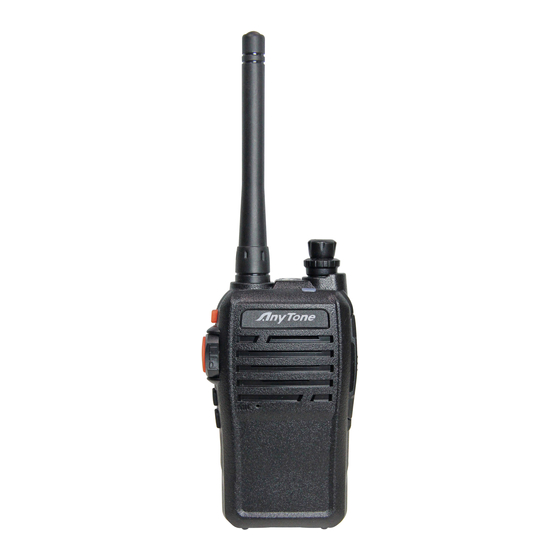
Page 18: Getting Acquainted
GETTING ACQUAINTED Professional FM Transceiver... - Page 19 GETTING ACQUAINTED Antenna POWER / VOLUME Switch: Rotate it clockwise to turn on the transceiver, rotate it counterclockwise until you hear the "click" to turn off the transceiver. When the transceiver is powered on, turn the knob clockwise to increase volume, or turn the knob counterclockwise to reduce the volume.
-
Page 20: Indicator Status And Beep Meanings
GETTING ACQUAINTED Indicator Status and Beep Meanings The red light flashes, and the transceiver emits a low voltage Warning on low voltage beep at intervals of 30 seconds. Transmitting The indicator will light red Receiving The indicator will light green Reading Frequency: Red light flashes Reading/Writing Frequency Writing Frequency: Green light flashes... -
Page 21: Auxiliary Functions
AUXILIARY FUNCTIONS Users can setup the key [PF1] and [PF2] to be one of the optional functions below: • Squelch off • Monitor • Current Channel Power Enquiry • Scan • Frequency Reverse • Talk Around • Battery Capacity Enquiry •... -
Page 22: Basic Operations
BASIC OPERATIONS Turn the Radio On & OFF When the radio is off, turn the [POWER]/[VOLUME] knob clockwise to turn on the transceiver. The transceiver will play a prompt tone, with voice feedback. It will audibly tell you what channel you are on once it has fully powered on. -
Page 23: Receiving
BASIC OPERATIONS Receiving When your transceiver receives a transmission, the LED light will light up. NOTE: You may not receive the call if your transceiver is set at a high squelch level. If the current channel is programmed with a mandatory decode (RX) tone (CTCSS, DCS, etc), the selected tone also must be present for the call to be heard. -
Page 24: Squelch Off
ADVANCED OPERATIONS Squelch Off Press the programmed key of 'Squelch off' [PF1]/[PF2], which will bypass the squelch. You will hear any noise on the frequency. By pressing this key again, the squelch level will be enabled again. By using this function you could monitor a weaker signal that might be too hard to normally be received (or break through the squelch). -
Page 25: Frequency Reverse
ADVANCED OPERATIONS programmed key again and the transceiver will respond with a beep that confirms you have disabled the ‘scan’ function and will return to the previous channel before scanning was activated. Please refer to the other scanning options in the 'advanced operations' to understand additional ‘scan’ options. Frequency Reverse Press the programmed key of ‘Frequency Reverse’... -
Page 26: Power Switch
ADVANCED OPERATIONS full. When the battery level is “1” (6.1V), the LED will light red. The transceiver will voice prompt users to charge the battery soon and will automatically disable TX. Power Switch Press the programmed key of ‘Power Switch’ [PF1]/[PF2], the transceiver will change the current channel power and announce the new power setting. -
Page 27: Ctcss / Dcs Encode And Decode
ADVANCED OPERATIONS CTCSS / DCS Encode and Decode When you set up the transceiver with CTCSS and DCS tones: CTCSS/ DCS Encode: Will transmit your selected CTCSS or DCS tone CTCSS/ DCS Decode: Will receive a transmission only if it carries your selected CTCSS or DCS tone. -
Page 28: Signaling Relations Setup
ADVANCED OPERATIONS If the calling party uses "C23" to call, Radio A and Radio B will receive the call. If the calling party uses"CC5" to call, Radio C and Radio D will receive the call. If the calling party uses "CCC" to call, All Radios will receive the call. This transceiver is set with 16 groups of DTMF codes (you can set what Call 1 and Call 2 use for each channel) Remote Stun, Remote Kill and Remote Waking. -
Page 29: Wide / Narrow Band Setup
ADVANCED OPERATIONS the party be heard. OR: As long as a matching CTCSS/DCS signal or a DTMF signal is received, calling of the other party can be heard. Wide / Narrow Band Setup According to the laws of various countries on frequency spectrum, you can set communication for (25k) wide band or (12.5k) narrow band. -
Page 30: Time-Out Timer
ADVANCED OPERATIONS Time-out Timer The purpose of Time-out-Timer is to restrict the transceiver from accidental long-term transmissions. If the transmission time goes beyond the preset time limit, the transceiver will stop transmitting and warn the user and make a beep sound. Users can set TOT timer by programming software. -
Page 31: Priority Scan Setup
ADVANCED OPERATIONS Priority Scan Setup There are two priority-channel settings that you can set the transceiver to have: "fixed" or "selected". A “fixed” priority channel is one main channel selected by software. A “selected” priority channel is the current channel selected by the channel knob. If a transmission is received on a channel and the radio stops to listen to the transmission it will ‘look back’... -
Page 32: Expand Frequency
ADVANCED OPERATIONS Selected + Talk Back: The Push-to-Talk Button will default to the channel knob selected channel unless you press the PTT following receiving a transmission found during scanning (before scanning resumes) If you intend to communicate quickly with those during scanning – this is the preferred option. -
Page 33: Resume Factory Default
ADVANCED OPERATIONS Resume Factory Default If your transceiver begins acting abnormally, you can set all functions and channels back to the ‘Factory Default’. When the radio is off, press the [PTT] and [PF1] key at the same time as you are switching on your transceiver. -
Page 34: Programming Software Starting(Uses The Windows Operating System)
Please plug the programming cable into the USB port of the PC device, and then connect it to the transceiver. (A Genuine FTDI cable from AnyTone Tech is recommended) Double click "ANILE-8R" shortcut icon, or click the ANILE-8R item in the "START" menu to open the programming software interface. -
Page 35: Technical Specifications
TECHNICAL SPECIFICATIONS General Adjacent Channel ≥60dB ≥60dB Selectivity VHF:136~174MHz Frequency Range UHF: 400~520MHz Intermodulation ≥60dB ≥60dB Channel Capacity 16 channels Spurious Rejection ≥80dB ≥80dB 25KHz (Wide Band) Audio Response 6dB/per interval 6dB/per interval Channel Spacing 12.5KHz (Narrow Band) Hum & Noise ≥50dB ≥45dB Phase-locked Step... -
Page 36: Trouble Shooting Guide
TROUBLE SHOOTING GUIDE Problem Corrective Action A.The battery may be depleted. Recharge or replace the battery. B.The battery may not be installed correctly. Remove the battery and install it again. No power C.The power switch is broken; Contact local dealer for repair. D.Battery tabs or the connection is broken;... - Page 37 TROUBLE SHOOTING GUIDE Can not power on or frequent Check if the battery is making good contact and is locked in place. power off The transmitting audio gets low Check if the MIC hole is plugged. If you cannot diagnose the issue or intermittent -contact local dealer for repair.
-
Page 38: Attached Chart
ATTACHED CHART CTCSS Frequency Chart 67.0 97.4 23 141.3 34 179.9 45 225.7 69.3 100.0 24 146.2 35 183.5 46 229.1 71.9 103.5 25 151.4 36 186.2 47 233.6 74.4 107.2 26 156.7 37 189.9 48 241.8 77.0 110.9 27 159.8 38 192.8 49 250.3 79.7 114.8 28 162.2 39 196.6 50 254.1... -
Page 39: Dcs Chart
ATTACHED CHART DCS Chart NOTE: 1. "N" stands for positive code. "I" stands for inverted code. 232 groups of DCS in total. 2. Overstriking marks are non-standard DCS. Professional FM Transceiver... -
Page 40: Fcc Compliance
FCC COMPLIANCE Usage of Your Transceiver on Part 90 (Commercial) and Part 97 (Amateur) Frequencies Changes or modifications to this device not expressly approved by ANYTONE could void the user's authorization to operate this device. This device complies with part 90 of the FCC Rules. Operation is subject to the following two conditions:(1)This device may not cause harmful interference, and (2) this device must accept any interference including received, interference that may cause undesired operation. -
Page 41: Limited Warranty (United States)
LIMITED WARRANTY (UNITED STATES) You MUST file your warranty information online at: AnyToneTech.com within 45 days of purchase. will repair or replace, at its option without charge, subject to the exclusions set forth below, any Two-Way -Radio transceiver which fails due to a defect in material or workmanship within ONE year following the initial consumer purchase. -
Page 42: Anytone Tech's Letter To You
ANYTONE TECH’S LETTER TO YOU: specializes in communication equipment, but even more important than communication with others - is your communication with God. To become a Christian and receive salvation is the greatest step you can take with God. To be real it must be a personal commitment from the heart.
Need help?
Do you have a question about the ANILE-8R and is the answer not in the manual?
Questions and answers