
Related Manuals for PowerWalker PowerWalker VFI 6000T LCD L


Summary of Contents for PowerWalker PowerWalker VFI 6000T LCD L
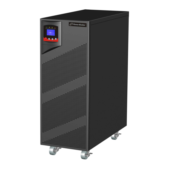
- Page 1 Online UPS PowerWalker VFI 6000T LCD (L) PowerWalker VFI 10000T LCD (L) Manual (EN) Uninterruptible Power Supply System...
-
Page 2: Table Of Contents
CONTENT: 1. Safety and EMC Instructions .............. 1 1.1 Installation ..................1 1.2 Operation ..................2 1.3 Maintenance, Servicing and Faults ..........2 1.4 Transport ..................3 1.5 Storage .................... 3 1.6 Standards ..................4 2. Description of Commonly Used Symbols ......... 5 3. - Page 3 8. Battery Maintenance ................51 9. Communication Port ................52 9.1 USB Interface ................52 9.2 Dry contact Interface ..............52 9.3 RS-232 Interface(optional) ............52 9.4 Intelligent slot................. 53 10. Software Installation ................ 54...
-
Page 4: Safety And Emc Instructions
1. Safety and EMC Instructions Please read carefully the following user manual and the safety instructions before installing the unit or using the unit! 1.1 Installation This is permanently connected equipment, and it must be installed by qualified maintenance personnel. ... -
Page 5: Operation
With the installation of the equipment, the sum of the leakage current of the UPS and the connected load does not exceed 5% of rated value of input current. Do not block ventilation openings in the UPS’s housing. Ensure allow at least 50cm of space on front and rear of the UPS. -
Page 6: Transport
Before carrying out any kind of service and/or maintenance, isolate UPS and disconnect the batteries. Verify that no current is present and no hazardous voltage exists in the capacitor or BUS capacitor. Batteries must be replaced only by qualified personnel. ... -
Page 7: Standards
1.6 Standards * Safety IEC/EN 62040-1 * EMI Conducted Emission......:IEC/EN 62040-2 Category C3 Radiated Emission......:IEC/EN 62040-2 Category C3 * EMS ESD...........:IEC/EN 61000-4-2 Level 3 RS.............:IEC/EN 61000-4-3 Level 3 EFT............:IEC/EN 61000-4-4 Level 4 SURGE..........:IEC/EN 61000-4-5 Level 4 CS………………………….…………...:IEC/EN 61000-4-6 Level 3 MS……………………………………..: IEC/EN 61000-4-8 Level 3 Voltage Dips………………………..: IEC/EN 61000-4-11... -
Page 8: Description Of Commonly Used Symbols
2. Description of Commonly Used Symbols Some or all of the following symbols may be used in this manual. It is advisable to familiarize yourself with them and understand their meaning:... -
Page 9: Introduction
Model No. on the rear panel of the UPS. Model No. Type Model No. Type PowerWalker PowerWalker VFI Extended VFI 6000T LCD 6000T LCD L Standard backup time PowerWalker... -
Page 10: Electrical Specifications
HE mode with high efficiency ≥0.96, save power expense for user. Input or output ISO transformer compatibility. Start-able without battery. 3.2 Electrical specifications INPUT PowerWalker PowerWalker Model No. VFI 6000T LCD (L) VFI 10000T LCD (L) Phase Single Voltage... -
Page 11: Operating Environment
*The load capacity would be derated to 90% automatically when the output voltage is adjusted to 208VAC. **The overload capacity would be derated automatically in Line mode while the circumstance temperature is larger than 35 degree. BATTERIES PowerWalker PowerWalker Model No. VFI 6000T LCD VFI 10000T LCD Internal BAT 20×12V 7Ah... -
Page 12: Typical Backup Time (Typical Values At 25°C In Minutes)
3.4 Typical Backup Time (Typical values at 25°C in minutes) Model No. 100 % Load PowerWalker VFI 6000T LCD PowerWalker VFI 10000T LCD 3.5 Dimensions and Weights Dimensions W×H×D Net Weight Model No. (mm) (kg) PowerWalker 260 x 708 x 550... - Page 13 PowerWalker VFI 6000T LCD (L) PowerWalker VFI 10000T LCD (L) Fig. 3-1 Back View of PowerWalker VFI 6000T LCD (L)/ PowerWalker VFI 10000T LCD (L)
-
Page 14: Installation
4. Installation The system may be installed and wired only by qualified electricians in accordance with applicable safety regulations! When installing the electrical wiring, please note the nominal amperage of your incoming feeder. 4.1 Moving to The Installation Site The series UPS has wheels making it easy to move the UPS to the installation site after it has been unpacked. -
Page 15: Input And Output Power Wires And Protective Earth Ground Installation
2. Check all packaging materials to ensure that no items are missing. The shipping package contains: ● A UPS ● A user manual ● A USB cable ● A RS232 cable (optional) ● A parallel port cover plate ●Terminal splices 12pcs (using for the wire connection on input terminal) ●... - Page 16 4.3.2 Installation For safety, please cut off the mains power switch and battery fuse before installation! Use cable cross section and protective device specification Model PowerWalker VFI PowerWalker VFI 6000T LCD (L) 10000T LCD (L) Protective earthing conductor (8AWG) 10 mm...
- Page 17 3) Open the terminal block cover located on the rear panel of UPS, please refer to the appearance diagram. 4) For PowerWalker VFI 6000T LCD UPS, it is recommended to select the UL1015 8AWG/6mm or other insulated wire which complies with AWG Standard for the UPS input and output wirings.
- Page 18 8) Connect other input and output wires to the corresponding input and output terminals according to the following diagram. 9) It is requested to use the accessorial terminal splices which can be compacted on the wires tightly, to ensure the connection between the wires and the terminal block is reliable.
-
Page 19: Operating Procedure For Connecting With The External Battery (Only For "S" Model)
8AWG/6mm respectively or other insulated wire which complies with AWG Standard for the UPS battery wirings. 3. For PowerWalker VFI 10000T LCD, select the UL1015 6AWG/10mm respectively or other insulated wire which complies with AWG Standard for the UPS battery wirings. -
Page 20: Epo Connection
Set the external battery pack breaker in “OFF” position and connect the 20 pieces of batteries in series. Connect the external battery pack to the battery terminals. Check the polarity of connection is correct. Set the breaker of the battery pack in the “ON” position. Set the mains input breaker in the “ON”... -
Page 21: Operation
5. Operation 5.1 Display Panel The UPS has a four-button dot matrix LCD with dual color backlight. Standard back-light is used to light up the display with white text and a blue background. When the UPS has a critical alarm, the backlight changes the text to dark amber and the background to amber. - Page 22 When displaying default UPS status summary Enter main screen, press this button for >1s to enter the menu main menu tree Press this button for >1s to exit the present menu Exit main to default system status display menu without menu executing a command or changing a setting Press this button for >100ms&<1s to scroll up the...
- Page 23 Note: ●: Lightened constantly △ : #1-#4 Lightened circularly ★: Flashing ↑: Depended on the fault/warning status or other status Table 5-3 Alarm definition UPS condition Buzzer status Fault active Continuous Warning active Beep every second Beep every 4 seconds, if battery low, buzzer Beep Battery output every second Bypass output...
-
Page 24: Operating Mode
UPS operating status Battery information Input Output 220 V 220 V UPS output 273.0 V information 60 Hz 60 Hz 100% 5400 W Utility input Load information information Fig. 5-2 The default LCD display The more detailed operation of LCD is illustrated in the chapter of 5.4. 5.2 Operating Mode The different graphic symbol could be displayed corresponding to current operating mode or status. - Page 25 5.2.2 Battery mode The example of LCD display in battery mode is shown in the following diagram. The symbol of operating in Battyer mode Input Output 220 V 273.0 V 0 Hz 60 Hz 100% 5400 W Fig. 5-4 Battery mode When the UPS is running in battery mode, the buzzer beeps once every 4 seconds.
- Page 26 5.2.4 Bypass without output The LCD display in bypass mode without output is shown in the following diagram. The symbol of operating in Bypass mode without output Input Output 220 V 273.0 V 60 Hz 0 Hz Fig. 5-6 Bypass mode without output 5.2.5 HE mode (High Efficiency mode) It is also called economy mode.
- Page 27 It is attention that the transfer time of UPS output from HE mode to battery mode is about 10ms. But it is still too long for some sensitive load. 5.2.6 Converter mode In converter mode, the UPS would free run with fixed output frequency (50Hz or 60Hz).
- Page 28 The symbol of Warning Input Output 220 V 220 V 273.0 V 60 Hz 60 Hz 100% 5400 W Fig. 5-9 Warning 5.2.8 Fault When the fault occurs, it illustrates that some fatal problems happened, the UPS would directly cut off the output or transfer to bypass, and keep alarming.
- Page 29 The symbol of overload Input Output 220 V 220 V 273.0 V 60 Hz 60 Hz 120% 6480 W Fig. 5-11 Overload While doing the battery test, LEDs would be lighted circularly, and the symbol of battery test would be shown on the display. The symbol of battery test Input Output...
-
Page 30: Turning On And Turning Off Ups
5.3 Turning On and Turning Off UPS Attention: The UPS could only be turning on while connecting with the mains at the first time. Attention: Please switch off the connected loads first before turning on the UPS, and switch on the loads one by one after the UPS is turned on. -
Page 31: Lcd Operation
5.3.3 Turning off UPS with mains To turn off the inverter of UPS by pressing button continuously for more than 3s and the buzzer will beep for 3s. The UPS will turn into Bypass mode at once. When completing the above action, UPS output voltage is still present. - Page 32 WELCOME UPS status Alarm # 41 Event log Battery Volt: 220V Battery charging Charger level:100% Measurements Status: Increase mode Para Num: 2 Running time: 0001: 03: 01: 00 Control Identification Settings Fig. 5-14 Main menu tree...
- Page 33 5.4.2 The UPS status menu on the menu of “UPS status”, the display would By pressing enter the next UPS status menu tree. The content of UPS status menu tree is same as the default UPS status summary menu. By pressing >1s, the display would return the last main menu tree.
- Page 34 5.4.3 The event log menu on the menu of “Event log”, the display would enter By pressing the next event menu tree. All the old event, alarm and fault have been recorded here. The information includes the illustration, the event code, and the operating time of UPS when the event happened.
- Page 35 5.4.4 The measurement menu on the menu of “Measurement”, the display would By pressing enter the next measurement menu tree. A lot of detailed useful information could be checked here, Ex. the output voltage and frequency, the output current, the load capacity, the input voltage and frequency, etc.
- Page 36 5.4.5 The control menu on the menu of “Control”, the display would enter By pressing the next control menu tree. Single UPS turn off: is one command to turn off one UPS which is operated currently in a parallel system, and other UPSs continue working to supply the load in the parallel system.
- Page 37 Fig. 5-18 Control menu tree...
- Page 38 Example: clear EPO status By press <1s Clear EPO status Status:EPO active Clear:no By press <1s Status:EPO active Clear:yes By press >1s Status:EPO inactive Clear:no Note: First make sure the EPO signal is inactive or the LCD will show below information and the EPO active status couldn’t be cleared. By press <1s Status:EPO signal...
- Page 39 Fig. 5-20 Identification menu tree 5.4.7 The setting menu Please contact your local distributor for further information before using the settings. Some settings would change the specification, and some settings would enable or disable some functions. The unsuitable option set by user may result in potential failures or protecting function loss, even directly damage the load, battery or UPS.
- Page 40 Fig. 5-21 Setting menu tree on the menu of “Identification”, the display would enter the By press next setting menu tree if “User password” is disabled. If “User password” is enabled, the user should enter the password by press , and , then enter the next setting menu tree.
- Page 41 Table 5-4 Submenu item Optional Values Default value User password enabled/disabled disabled Audio alarm enabled/disabled enabled Rated output voltage 208/220/230/240V 230V Output frequency autosensing/50/60Hz autosensing Power strategy** normal/high efficiency/ converter normal DC start enabled/disabled enabled Site wiring fault alarm enabled/disabled enabled Ambient temperature...
- Page 42 Example: set rated output voltage value Setting menu tree By press <1s The option would flash Output voltage Output voltage <230V> <230V> By press <1s By press <1s, to select the wanted option Output voltage <220V> By press >1s, to confirm the setting The option would stop flashing Output voltage after being confirmed...
-
Page 43: Special Function
6. Special Function The series UPS has some special functions, which could satisfy some special application of user. And the functions have own features, please contact your local distributor for further information before using the function. 6.1 HE Function 6.1.1 Brief introduction of HE function If HE function is set to enable, after the UPS is turned on, the power used by the load is directly supplied from the mains power via internal filter while the utility power is in normal range, so the high... -
Page 44: Converter Function
6.2 Converter Function 6.2.1 Brief introduction of Converter function In converter mode, the UPS would free run with fixed output frequency (50Hz or 60Hz). Once the mains power is loss or abnormal, the UPS would transfer to Battery mode and the load is supplied continuously. - Page 45 6.3.2 Parallel installation and operation How to install a new parallel UPS system: Before installing a new parallel UPS system, user need to prepare the input and output wires, the output breaker, and the parallel cable. Users need to use a standard 25-pin communication cable, which should have 25 cores, corresponding stitches and shield, as the UPS parallel cable.
- Page 46 IP_G IP_N IP_L OP_N OP_L OP_G BAT Ground BAT PACK #1 (For “S” model) IP_G IP_N IP_L OP_N OP_L OP_G BAT Ground BAT PACK #2 (For “S” model) TO UTILITY TO LOAD Fig. 6-1 Input and output Terminal Block wiring diagram...
- Page 47 Fig. 6-2 Parallel System Installation Diagram 10) Do not switch on the output breaker of each UPS, switch on the input breaker of the each UPS, the UPS should work in bypass with output, observe their display to check if there are any warning or fault information, measure the output voltage of each UPS separately to check if the voltage difference between them is less than 1V.
- Page 48 13) Press the button of one UPS, each UPS would start to turn on, after turning on, the UPSs should work parallel in the Line mode. How to join a new UPS to a parallel system: First the parallel system must be installed one main maintenance mechanical switch or static switch.
- Page 49 automatically, set the own maintenance switch of each UPS from “UPS” to “BPS”. Set the main maintenance switch or static switch from “UPS” to “BPS”, switch off the main output breaker and the main input breaker, and the UPSs would shut down. Ensure the UPSs shut down totally, remove the wanted UPS and reinstall the new UPS parallel system by following step 1) to 9) of last chapter - “install a new parallel UPS system”.
-
Page 50: Trouble Shooting
7. Trouble Shooting If the UPS system does not operate correctly, first check the operating information on the LCD display. Please attempt to solve the problem using the table below. If the problem still persists, consult your dealer. 7.1 Trouble Shooting According To Warning Indication Problem Displayed Possible cause Remedy... - Page 51 Over Charge Battery is over The UPS will turn off the charged charger until the battery voltage is normal Model Pin Error UPS internal fault Consult dealer. Ambient Over The ambient Check the environment Temperature temperature is too ventilation. high Heatsink Over Inside temperature of Check the ventilation of UPS...
-
Page 52: Trouble Shooting According To Fault Indication
7.2 Trouble Shooting According To Fault Indication Problem Displayed Possible cause Remedy Inv Overload Fault Overload Check the loads and remove some non-critical loads. Check if some loads are failed. Byp Overload Fault Overload Check the loads and remove some non-critical loads. Check if some loads are failed. -
Page 53: Trouble Shooting In Else Cases
7.3 Trouble Shooting In Else Cases Problem Possible cause Remedy No indication, no No input voltage Check the building wiring and warning tone even input cable. though system is Check if the input breaker is connected to mains closed. power supply Press On-Switch “I”... -
Page 54: Battery Maintenance
8. Battery Maintenance Battery replacement should be performed by qualified personnel. This series UPS only requires minimal maintenance. The battery used for standard models are value regulated sealed lead-acid maintenance free battery. These models require minimal repairs. The only requirement is to charge the UPS regularly in order to maximize the expected life of the battery. -
Page 55: Communication Port
9. Communication Port 9.1 USB Interface The USB port is compliance with USB 1.1 protocol for its communication software. 9.2 Dry contact Interface This series UPS has independent dry contact interface. Please contact your local distributor for details. The following is the pin assignment and description of DB-9 connector. -
Page 56: Intelligent Slot
RS-232 communication port pin assignments Direction from Pin Signal name Function the UPS Unused Not applicable Transmit to external device Receive from external device In Unused Not applicable Signal common Not applicable Unused Not applicable Unused Not applicable Unused Not applicable Unused Not applicable 9.4 Intelligent slot... -
Page 57: Software Installation
Double-click the icon to use the monitor software (as above). You can schedule UPS shutdown/start-up and monitor UPS status through Detail instructions please refer to the e-manual in the software. Check www.powerwalker.com/winpower.html from time to time to get the latest version of monitoring software. - Page 58 614-09335-00...
Need help?
Do you have a question about the PowerWalker VFI 6000T LCD L and is the answer not in the manual?
Questions and answers