Table of Contents
Advertisement
Available languages
Available languages
Disclaimer
The information in this document is subject to change without notice. The
manufacturer makes no representations or warranties with respect to the contents
hereof and specifically disclaims any implied warranties of merchantability or
fitness for any particular purpose. The manufacturer reserves the right to revise this
publication and to make changes from time to time in the content hereof without
obligation of the manufacturer to notify any person of such revision or changes.
Federal Communications Commission (FCC)
This equipment has been tested and found to comply with the limits for a Class B
digital device, pursuant to Part 15 of the FCC Rules. These limits are designed to
provide reasonable protection against harmful interference in a residential
installation. This equipment generates, uses, and can radiate radio frequency
energy and, if not installed and used in accordance with the instructions, may cause
harmful interference to radio communications. However, there is no guarantee that
interference will not occur in a particular installation. If this equipment does cause
harmful interference to radio or television reception, which can be determined by
turning the equipment off and on, the user is encouraged to try to correct the
interference by one or more of the following measures:
•
Reorient or relocate the receiving antenna
•
Increase the separation between the equipment and the receiver
•
Connect the equipment onto an outlet on a circuit different from that to
which the receiver is connected
•
Consult the dealer or an experienced radio/TV technician for help
Shielded interconnect cables and a shielded AC power cable must be employed with
this equipment to ensure compliance with the pertinent RF emission limits
governing this device. Changes or modifications not expressly approved by the
system's manufacturer could void the user's authority to operate the equipment.
Declaration of Conformity
This device complies with part 15 of the FCC rules. Operation is subject to the follow-
ing conditions:
•
This device may not cause harmful interference.
•
This device must accept any interference received, including interference
that may cause undesired operation.
This device is in conformity with the following EC/EMC directives:
EN 55022
EN 61000-3-2
EN 61000-3-3
EN 55024
EN 60950
CE marking
Limits and methods of mesurement of radio disturbance char-
acteristics of information technology equipment
Disturbances in supply systems caused
Disturbances in supply systems caused by household appli-
ances and similar electrical equipment " Voltage fluctuations"
Information technology equipment-Immunity characteristics-
Limits and methods of measurement
Safety for information technology equipment including electri-
cal business equipment
H81H3-M4 USER MANUAL
Advertisement
Table of Contents

Related Manuals for ECS H81H3-M4


Summary of Contents for ECS H81H3-M4
-
Page 1: Declaration Of Conformity
Disturbances in supply systems caused by household appli- EN 61000-3-3 ances and similar electrical equipment “ Voltage fluctuations” EN 55024 Information technology equipment-Immunity characteristics- Limits and methods of measurement Safety for information technology equipment including electri- EN 60950 cal business equipment CE marking H81H3-M4 USER MANUAL... -
Page 2: Table Of Contents
TABLE OF CONTENTS Preface Brief Introduction Specifications..................1 Motherboard Components..............3 Header Pin Definition and Jumper Settings.........4 I/O Ports....................6 Multi-language Quick Installation Guide English....................7 Brazilian Portuguese................9 Hindi........................11 French......................13 Deutsch....................15 Russian....................17 Spanish....................19 Indonesian.....................21 Arabic.......................23 Simplified Chinese................25 Korean......................27 H81H3-M4 USER MANUAL... -
Page 3: Brief Introduction
Brief Introduction Specifications ® • LGA1150 socket for 4 Generation Intel Core Family/ Pentium/Celeron Processors Note: Please go to ECS website for the latest CPU support list. ® Chipset • Intel H81 Chipset Memory • Dual-channel DDR3 memory architecture •... - Page 4 - Supports Multi-language - Supports AC’97/HD Audio auto detect (default) - Supports LOAD NON DISK UTILITY in BIOS BOOT Page Form Factor • 190mm x 170mm QR Code for the complete manual download on ECS website: http://www.ecs.com.tw H81H3-M4 USER MANUAL...
-
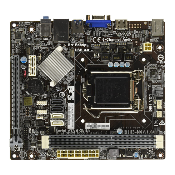
Page 5: Motherboard Components
PCI Express slot for graphics interface 16. CLR CMOS Clear CMOS jumper 17. F_AUDIO Front panel audio header 18. PCIE1 PCI Express x1 slot 19. ME_UNLOCK ME unlock header-for factory use only 20. ATX12V 4-pin +12V power connector H81H3-M4 USER MANUAL... -
Page 6: Header Pin Definition And Jumper Settings
USB Port B (-) USB Port A (-) USB Port A (+) USB Port B (+) Ground Ground Not Connected LPC Signal LPC Signal LPC Signal LPC Signal Ground PIN 1 Power +3.3V LPC signal Reset Clock H81H3-M4 USER MANUAL... - Page 7 Chassis cover is removed is closed ME_UNLOCK UNLOCK LOCK CLR_CMOS Jumper 1-2: NORMAL 2-3: CLEAR CMOS Before clearing the CMOS, make sure to turn off the system. CLR_CMOS USBPWR_F (Front Panel USB Power Select Jumper) 5VSB (Default) H81H3-M4 USER MANUAL...
-
Page 8: I/O Ports
It can be connected to an external CD/DVD player, Tape player or other audio devices for audio input. 9. Line-out(lime) It is used to connect to speakers or headphones. 10. Microphone(pink) It is used to connect to a microphone. H81H3-M4 USER MANUAL... -
Page 9: Multi-Language Quick Installation Guide
Hardware Installation Guide Installation Steps Step 1. Installation of the CPU and CPU Cooler: 1-1. Pull up the lever away from the 1-2. Rotate and press down the fastener socket. Align the CPU cut edge with the of CPU fan to the motherboard through indented edge of the CPU socket. - Page 10 Step 5. Connecting Cables and Power Connectors: a. Connect the SATA hard drive to its b. Connect SATA power connector to the SATA cable SATA device c. Connect 24-pin power cable d. Connect 4-pin power cable Please note that when installing 24-pin The ATX_12V 4-Pin power connector is used power cable, the latches of power cable to provide power to the CPU.
-
Page 11: Brazilian Portuguese
Manual de Instalação de Hardware Etapas para instalação Passo 1. Instalação da CPU e da CPU Refrigeração (Cooler): 1-1. Puxe a alavanca para fora do 1-2. Gire e pressione para baixo a soquete. Alinhe o lado da CPU com o alavanca de fecho da ventoinha da CPU lado correto do soquete do processador. - Page 12 Passo 5. Conexão de cabos e conectores de alimentação: a. Conecte o disco rígido SATA ao seu b. Ligue o conector de alimentação SATA ao cabo SATA. c. Ligue o cabo de alimentação 24 pinos. d. Ligue o cabo de alimentação de 4-pinos. Por favor note que ao instalar o cabo de O conector de alimentação ATX_12V de 4-Pin alimentação de 24 pinos, as travas do...
-
Page 13: Hindi
1 CPU 1-1. 1-2. CPU 2-1. DIMM 2-2. DIMM 3-1. 3-2. - Page 14 SATA SATA SATA SATA ATX_12V 4- ATX_12V BIOS ( BIOS (POST) <DEL> POST BIOS CMOS...
-
Page 15: French
1-1. Ecartez le levier du socket. Alignez 1-2. Tournez et appuyez sur la le bord coupé du CPU avec le bord correspondant sur le socket du CPU. carte mère à travers les trous pour Placez soigneusement le CPU dans la bonne de pâte thermique sur la surface du CPU. - Page 16 a. Connectez le disque dur SATA à son câble SATA au périphérique SATA broches broches connecteur ATX correspondent connecteur ATX_12V. parfaitement. Une fois que les étapes ci-dessus ont été e ectuées, connectez les périphériques tels que le clavier, la et allumez le système.
-
Page 17: Deutsch
1-2. Lösen Sie durch eine Drehung die Pushpins 1-1. Lösen Sie den Hebel vom des CPU-Kühlers und richten Sie diese mit den CPU-Sockel. entsprechenden Löchern Kunststo abdeckung und richten Sie die aus und drücken Sie die Kerbe der CPU mit der entsprechenden Pushpins nach unten bis sie einrasten. - Page 18 b. Schließen Sie die SATA-Stromanschlusskabel a. Schließen Sie das/die SATA-Kabel der an den SATA-Geräten an c. Stecken Sie das 24-Pin-Stromversorgungskabel d. Stecken Sie das 4-Pin-Stromversorgungsk in den entsprechenden Anschluss auf der abel in den entsprechenden Anschluss auf Der ATX_12V 4-Pin-Anschluss versorgt die CPU mit der einen Seite des 24-Pin- Stromversorgungskabels am ATX-Anschluss der einen Seite des 4-Pin-Stromversorgungska...
-
Page 19: Russian
1-1. 1-2. 3-1. 3-2. - Page 20 SATA SATA SATA SATA ATX_12V. ATX_12V. BIOS BIOS ( BIOS POST ( <DEL > CMOS). BIOS “Load Default CMOS...
-
Page 21: Spanish
Guía de instalación del hardware Pasos para realizar la instalación Paso 1. Instalación de la CPU y sistema de refrigeración de la CPU: 1-1. Tire de la palanca hacia arriba, 1-2. Gire y presione hacia abajo la sujeción apartándola del zócalo. Alinee el base borde recortado de la CPU con el a través de los ori cios, para instalar... - Page 22 Paso 5. Conexión de los cables y los conectores de alimentación: a. Conecte el disco duro SATA al cable b. Conecte el conector de alimentación SATA SATA. c. Conecte el cable de alimentación de 24 d. Conecte el cable de alimentación de 4 pines.
-
Page 23: Indonesian
Panduan Pemasangan Perangkat Keras Langkah-Langkah Pemasangan Langkah 1. Pemasangan CPU dan Pendingin CPU: 1-1. Tarik tuas dari soket. Luruskan 1-2. Putar dan tekan penahan kipas CPU tepi pemisah CPU dengan tepi ke lubang tembus motherboard untuk bertakik dari soket CPU. Pasang CPU memasang kipas CPU pada tempatnya. - Page 24 Langkah 5. Menyambungkan Kabel dan Konektor Daya: a. Sambungkan hard drive SATA ke kabel b. Sambungkan konektor daya SATA ke SATA perangkat SATA c. Sambungkan kabel daya 24 pin d. Sambungkan kabel daya 4 pin Konektor daya ATX_12V 4 pin digunakan untuk kabel daya 24, kait pada kabel daya menyediakan daya ke CPU.
-
Page 25: Arabic
دﻟﻴﻞ ﺗﺮﻛﻴﺐ اﳌﻜﻮﻧﺎت اﻟﺼﻠﺒﺔ ﺧﻄﻮات اﻟﱰﻛﻴﺐ :اﻟﺨﻄﻮة رﻗﻢ 1. ﺗﺮﻛﻴﺐ وﺣﺪة اﳌﻌﺎﻟﺠﺔ اﳌﺮﻛﺰﻳﺔ وﻣﱪد وﺣﺪة اﳌﻌﺎﻟﺠﺔ اﳌﺮﻛﺰﻳﺔ 1-2 ﻗﻢ ﺑﺎﻹدارة واﻟﻀﻐﻂ ﻷﺳﻔﻞ ﻋﲆ ﻣﺸﺒﻚ ﻣﺮوﺣﺔ وﺣﺪة اﳌﻌﺎﻟﺠﺔ 1-1 اﺳﺤﺐ اﻟﺬ ر اع ﻷﻋﲆ ﺑﻌﻴﺪا ﻋﻦ اﳌﻘﺒﺲ. ﻗﻢ مبﺤﺎذاة اﻟﻄﺮف ﻣﺸﻘﻮق اﳌﺮﻛﺰﻳﺔ... - Page 26 :اﻟﺨﻄﻮة رﻗﻢ 5. ﻛﺒﻼت اﻟﺘﻮﺻﻴﻞ وﻣﻮﺻﻼت اﻟﻄﺎﻗﺔ ﺑﺎﻟﺠﻬﺎز ﻣﻦ ﻃ ﺮ ازSATA ب. ﻗﻢ ﺑﺘﻮﺻﻴﻞ ﻣﻮﺻﻞ اﻟﻄﺎﻗﺔ ﻣﻦ ﻃ ﺮ از اﻟﺨﺎص ﺑﻪSATA ﺑﻜﺒﻞSATA أ. ﻗﻢ ﺑﺘﻮﺻﻴﻞ ﻣﺤﺮك اﻷﻗ ﺮ اص ﻣﻦ ﻃ ﺮ از SATA د. ﻗﻢ ﺑﺘﻮﺻﻴﻞ ﻛﺒﻞ اﻟﻄﺎﻗﺔ اﳌﺰود ﺑﻌﺪد 4 دﺑﻮس 0ج.
-
Page 27: Simplified Chinese
CPU CPU 1-2. 1-1. C P U C P U C P U C P U C P U 2-1. 2-2. 3-1. 3-2. - Page 28 SATA SATA SATA SATA BIOS BIOS BIOS (POST) <D EL> BIOS POST BIOS BIOS...
-
Page 29: Korean
. CPU CPU 1-1. 1-2. . CPU . CPU 2-1. D I M M 2-2. DIMM 3-1. I / O 3-2. I / O I / O... - Page 30 a. SATA SATA b. SATA SATA c. 4 d. 4 ATX_12V 4 ATX_12V BIOS BIOS , BIOS Power-On Self Test (POST) <DEL> BIOS CMOS . (CPU,...
Need help?
Do you have a question about the H81H3-M4 and is the answer not in the manual?
Questions and answers