Table of Contents
Advertisement
Advertisement
Table of Contents

Related Manuals for ECS 915P-A


Summary of Contents for ECS 915P-A
- Page 3 Preface Copyright This publication, including all photographs, illustrations and software, is protected under international copyright laws, with all rights reserved. Neither this manual, nor any of the material contained herein, may be reproduced without written consent of the author. Version 1.2a Disclaimer The information in this document is subject to change without notice.
-
Page 4: Declaration Of Conformity
Declaration of Conformity This device complies with part 15 of the FCC rules. Operation is subject to the following conditions: • This device may not cause harmful interference, and • This device must accept any interference received, including interference that may cause undesired operation Canadian Department of Communications This class B digital apparatus meets all requirements of the Canadian Interference-causing Equipment Regulations. -
Page 5: Table Of Contents
T T T T T ABLE OF CONTENTS ABLE OF CONTENTS ABLE OF CONTENTS ABLE OF CONTENTS ABLE OF CONTENTS Preface Chapter 1 Introducing the Motherboard Introduction....................1 Feature......................2 Motherboard Components................4 7 7 7 7 7 Chapter 2 Installing the Motherboard Safety Precautions..................7 Choosing a Computer Case...............7 Installing the Motherboard in a Case............7... - Page 6 Power Management Setup............34 PCI/Plug and Play Setup.............35 BIOS Security Features..............36 CPU PnP Setup................37 Hardware Monitor...............38 Load Best Performance Settings..........39 Load Optimal Defaults..............39 Save Changes and Exit..............39 Discard Changes and Exit............39 Chapter 4 39 39 Using the Motherboard Software About the Software CD-ROM..............39 Auto-installing under Windows 98/ME/2000/XP........39 Running Setup................40 Manual Installation..................42...
-
Page 7: Introducing The Motherboard
SATA v1.0 compliant, supporting four SATA ports with maximum transfer rate up to 150 MB/s each. The 915P-A motherboard is equipped with advanced full set of I/O ports in the rear panel, including PS/2 mouse and keyboard connectors, COM1, LPT1, four USB ports, one op- tional LAN port, and audio jacks for microphone, line-in and 8-ch line out. -
Page 8: Feature
Feature Processor Processor The 915P-A uses an LGA775 type of Pentium 4 that carries the following features: • Accommodates Intel P4 Prescott processors • Supports a system bus (FSB) of 800/533MHz • Supports “Hyper-Threading” technology CPU “Hyper-Threading” technology enables the operating system into thinking it’s hooked up to two processors, allowing two threads to be run in parallel, both on separate “logical”... - Page 9 One 40-pin IDE low profile header that support two IDE devices • One floppy disk drive interface • Four 7-pin SATA connector The 915P-A motherboard supports UltraDMA bus mastering with transfer rates of 100/ 66 MB/s. Onboard LAN (Optional) Onboard LAN (Optional) The onboard LAN controller provides the following features: •...
-
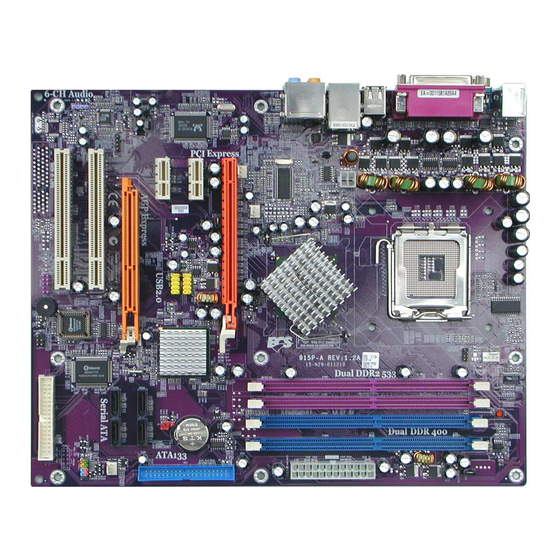
Page 10: Motherboard Components
Motherboard Components Introducing the Motherboard... - Page 11 Table of Motherboard Components LABEL COMPONENT 1 CPU Socket LGA775 socket for Pentium 4 CPUs 2 CPU_FAN1 CPU cooling fan connector 3 DIMM1~2 240-pin DDR2 SDRAM slots 4 DIMM3~4 184-pin DDR SDRAM slots 5 PWR1 Standard 24-pin ATX power connector 6 IDE1 Primary IDE channel 7 SATA1~4...
- Page 12 Memo Introducing the Motherboard...
-
Page 13: Installing The Motherboard
Chapter 2 Installing the Motherboard Safety Precautions • Follow these safety precautions when installing the motherboard • Wear a grounding strap attached to a grounded device to avoid damage from static electricity • Discharge static electricity by touching the metal case of a safely grounded object before working on the motherboard •... -
Page 14: Checking Jumper Settings
Do not over-tighten the screws as this can stress the motherboard. Checking Jumper Settings This section explains how to set jumpers for correct configuration of the motherboard. Setting Jumpers Use the motherboard jumpers to set system configuration options. Jumpers with more than one pin are numbered. -
Page 15: Checking Jumper Settings
Checking Jumper Settings The following illustration shows the location of the motherboard jumpers. Pin 1 is labeled. Jumper Settings Type Jumper Description Setting (default) 1-2: NORMAL 3-pin CLEAR CMOS 2-3: CMOS CLEAR Before clearing the CMOS, make sure to turn off the system. OPEN: WRITW UNPROTECT 2-pin JP11... -
Page 16: Connecting Case Components
Connecting Case Components After you have installed the motherboard into a case, you can begin con- necting the motherboard components. Refer to the following: Connect the CPU cooling fan cable to CPU_FAN1. Connect the case cooling fan connector to CHS_FAN1. Connect the Northbridge cooling fan connector to NB_FAN1. - Page 17 CPUFAN1: FAN Power Connectors Signal Name Function System Ground Power +12V +12V Sense Sensor CPU FAN control CHS_FAN1/NB_FAN1/AUX_FAN1: FAN Power Connectors Signal Name Function System Ground Power +12V +12V Sense Sensor PWR2: ATX 12V Power Connector Signal Name Ground Ground +12V +12V PWR1: ATX 24-pin Power Connector...
-
Page 18: Front Panel Connector
Front Panel Connector The front panel connector (PANEL1) provides a standard set of switch and LED connec- tors commonly found on ATX or micro-ATX cases. Refer to the table below for informa- tion: Signal Function Signal Function HD_LED_P Hard disk LED+ FP PWR/SLP *MSG LED+ HD_LED_N Hard disk LED- FP PWR/SLP *MSG LED-... -
Page 19: Installing Hardware
Installing Hardware Installing the Processor Caution: When installing a CPU heatsink and cooling fan make sure that you DO NOT scratch the motherboard or any of the surface-mount resistors with the clip of the cooling fan. If the clip of the cooling fan scrapes across the motherboard, you may cause serious damage to the motherboard or its components. -
Page 20: Cpu Installation Procedure
CPU Installation Procedure The following illustration shows CPU installation components. A. Unload the cap · Use thumb & forefinger to hold the lifting tab of the cap. · Lift the cap up and remove the cap completely from the socket. B. -
Page 21: Installing Memory Modules
Installing Memory Modules This motherboard accomodates four memory modules. It can support two 184-pin 2.5V unbuffered DIMM, DDR 400/333 or two 240-pin 1.8V DDR2 533/400. The total memory capacity is 2GB. Users please note that DDR & DDR2 can’t both be applied at the same time on this motherboard. - Page 22 Table A: DDR QVL (Qualified Vender List) The following DDR memory modules have been tested and qualified for use with this motherboard. Type Size Brand Chip 256MB A-DATA ADD8608A8A-5B 256MB Hynix HY5DU56822BT-D43 256MB KingMax KDL684T4AA-50 256MB Kingston 9905192-012.A01 256MB SAMSUNG K4H560838D-TCC4 256MB TwinMOS...
-
Page 23: Installing A Hard Disk Drive/Cd-Rom/Sata Hard Drive
Installing a Hard Dish Drive/CD-ROM/SATA Hard Drive This section describes how to install IDE devices such as a hard disk drive and a CD-ROM drive. About IDE Devices Your motherboard has one IDE channel interface. An IDE ribbon cable supporting two IDE devices is bundled with the motherboard. - Page 24 About SATA Connectors Your motherboard features four SATA connectors supporting a total of four drives. SATA , or Serial ATA (Advanced Technology Attachment) is the standard interface for the IDE hard drives which are currently used in most PCs. These connectors are well designed and will only fit in one orientation.
-
Page 25: Installing A Floppy Diskette Drive
Installing a Floppy Diskette Drive The motherboard has a floppy diskette drive (FDD) interface and ships with a diskette drive ribbon cable that supports one or two floppy diskette drives. You can install a 5.25-inch drive and a 3.5-inch drive with various capacities. The floppy diskette drive cable has one type of connector for a 5.25-inch drive and another type of connector for a 3.5-inch drive. -
Page 26: Installing Add-On Cards
AGP Express slot, we recommend users use one of the AGP graphics cards that have been tested by out company. See the “Supported AGP 8X/4X VGA Cards List” or visit our website at “http://www.ecs.com.tw” for the updated supported list. - Page 27 GeForce 4 MX440 ASUS V8170DDR GeForce 4 Ti4400 ELSA 725DVI GeForce 4 Ti4600 ELSA 925ViVo For the latest updates of the supported AGP VGA cards list, please visit ECS ELITEGROUP website for details. ECS ELITEGROUP website: http://www.ecs.com.tw Installing the Motherboard...
-
Page 28: Connecting Optional Devices
Follow these instructions to install an add-on card: Remove a blanking plate from the system case corresponding to the slot you are going to use. Install the edge connector of the add-on card into the expansion slot. Ensure that the edge connector is correctly seated in the slot. Secure the metal bracket of the card to the system case with a screw. - Page 29 AUDIO2: Front Panel Audio header This header allows the user to install auxiliary front-oriented microphone and line-out ports for easier access. Signal Name Signal Name Function AUD_MIC Front Panel Microphone input signal AUD_GND Ground used by Analog Audio Circuits AUD_MIC_BIAS Microphone Power AUD_VCC Filtered +5V used by Analog Audio Circuits AUD_F_R...
- Page 30 USB3/4: Front Panel USB header The motherboard has four USB ports installed on the rear edge I/O port array. Additionally, some computer cases have USB ports at the front of the case. If you have this kind of case, use auxiliary USB connector to connect the front-mounted ports to the motherboard. Signal Name Function USBPWR...
-
Page 31: Connecting I/O Devices
Connecting I/O Devices The backplane of the motherboard has the following I/O ports: PS2 Mouse Use the upper PS/2 port to connect a PS/2 pointing device. PS2 Keyboard Use the lower PS/2 port to connect a PS/2 keyboard. Parallel Port (LPT1) Use LPT1 to connect printers or other parallel communications devices. - Page 32 Memo Installing the Motherboard...
-
Page 33: Using Bios
Chapter 3 Using BIOS About the Setup Utility The computer uses the latest American Megatrends BIOS with support for Windows Plug and Play. The CMOS chip on the motherboard contains the ROM setup instructions for configuring the motherboard BIOS. The BIOS (Basic Input and Output System) Setup Utility displays the system’s configura- tion status and provides you with options to set system parameters. -
Page 34: Advanced Setup
Press DEL/F1 to enter SETUP Press the delete key or F1 to access the BIOS Setup Utility. CMOS Setup Utility -- Copyright (C) 1985-2004, American Megatrends, Inc. Standard CMOS Setup CPU PnP Setup Advanced Setup Hardware monitor Features Setup Load Best Performance settings Power Management Setup Load Optimal Defaults PCI / Plug and Play Setup... - Page 35 Updating the BIOS You can download and install updated BIOS for this motherboard from the manufacturer’s Web site. New BIOS provides support for new peripherals, improvements in performance, or fixes for known bugs. Install new BIOS as follows: If your motherboard has a BIOS protection jumper, change the setting to allow BIOS flashing.
- Page 36 Standard CMOS Setup This option displays basic information about your system. CMOS Setup Utility - Copyright (C) 1985-2004, American Megatrends, Inc. Standard CMOS Setup System Time 14: 02: 44 Help Menu System Date Wed 05/05/2004 Primary IDE Master Not Detected Primary IDE Slave Not Detected Use [ENTER], [TAB]...
- Page 37 Quick Boot (Enabled) If you enable this item, the system starts up more quickly because of the elimination of some of the power on test rutines. 1st/2nd/3rd Boot Device Use this item to determine the device order the computer used to look for an operating system to load at start-up time.
-
Page 38: Features Setup
Features Setup This page sets up some parameters for peripheral devices connected to the system. CMOS Setup Utility - Copyright (C) 1985-2004, American Megatrends, Inc. Features Setup OnBoard Floppy Controller Enabled Help Menu Serial Port1 Address 3F8/IRQ4 Onboard IR Port Disabled Allow BIOS to Enable or Parallel Port Address... - Page 39 ATA/IDE Configuration (Enhanced) The ATA/IDE option can be configured as either “Enhanced (default)” or “Compatible” in the BIOS configuration. Windows* 98SE and Windows* Me operating systems do not support Enhanced mode IDE/Serial ATA resources for more than four devices. If the ATA/IDE option is set to Enhanced mode, the operating installation will not be able to recognize the drive, and the installation will fail.
-
Page 40: Pci/Plug And Play Setup
Suspend Mode (S1 (POS)) Use this item to define how your system suspends. In the default, S1(POS), the suspend mode is equivalent to a software power down. If you select S3 (STR), the suspend mode is a suspend to RAM, i.e., the system shuts down with the exception of a refresh current to the system memory. -
Page 41: Bios Security Features
Plug & Play Aware O/S (Yes) This itme select which, the BIOS or the operating system, will configure all the devices in the system. If set NO, the BIOS configures the system; set YES, the operating system configure Plug and Play devices. Primary Graphics Adapter (PCI-E VGA) This itme indicates if the primary graphics adapter uses the PCI-E VGA, PCI VGA, or AGP- E VGA. -
Page 42: Cpu Pnp Setup
CPU PnP Setup This page helps you manually configure the CPU of this motherborad. The system will automatically detect the type of installed CPU and make the appropriate adjustments to these items on this page. CMOS Setup Utility - Copyright (C) 1985-2004, American Megatrends, Inc. CPU PnP Setup Manufacturer: Intel... -
Page 43: Hardware Monitor
CPU Voltage default Value (1.3875V) This item identifies the CPU voltage default value. The value may change depending on the CPU you installed on this motherboard. CPU Voltage Control (Auto) This item enables users to adjust the CPU voltage. We strongly recommend users leave this item at its default value. -
Page 44: Load Best Performance Settings
Load Best Performance Settings If you select this item and press Enter a dialog box appears. If you select [OK], and then Enter, the Setup Utility loads a set of best-performance default values. These default are quite demanding and your system might not function properly if you are using slower memory chips or other low-performance components. -
Page 45: Using The Motherboard Software
Chapter 4 Using the Motherboard Software About the Software CD-ROM The support software CD-ROM that is included in the motherboard package contains all the drivers and utility programs needed to properly run the bundled products. Below you can find a brief description of each software program, and the location for your motherboard version. -
Page 46: Running Setup
Setup Tab Setup Click the Setup button to run the software installation program. Select from the menu which software you want to install. Browse CD The Browse CD button is the standard Windows command that allows you to open Windows Explorer and show the contents of the support Before installing the software from Windows Explorer, look for a file named README.TXT, INSTALL.TXT or something similar. - Page 47 Click Next. The following screen appears: Check the box next to the items you want to install. The default options are recommended. Click Next run the Installation Wizard. An item installation screen appears: Follow the instructions on the screen to install the items. Drivers and software are automatically installed in sequence.
-
Page 48: Manual Installation
Manual Installation Insert the CD in the CD-ROM drive and locate the PATH.DOC file in the root directory. This file contains the information needed to locate the drivers for your motherboard. Look for the chipset and motherboard model; then browse to the directory and path to begin installing the drivers. - Page 49 Caractéristiques Processeur Processeur La 915P-A utilise un type LGA775 de Pentium 4 présentant les fonctionnalités suivantes: • Reçoit des processeurs Intel P4 Prescott • Support un bus système (FSB) de 800/533 MHz • Supporte le CPU de technologie “Hyper-Threading” La technologie “Hyper-Threading” permet au système d’exploitation de penser qu’il est connecté...
- Page 50 Audio Audio • Conforme à la spécification Azalia, prenant en charge 8 canaux DAC avec SNR > 95Db • Compatibilités: 192/96/48/44.1 KHz avec 24/20/16 bits • Support de port d’E/S à 8 prises intelligentes • Détection de prise étendue via RNM (resistors network method) pouvant être utilisée pour surveiller l’état de branchement de chaque prise •...
- Page 51 Leistungsmerkmale Prozessor Prozessor Der 915P-A benutzt einen Pentium 4 des Typs LGA775 und besitzt folgende Eigenschaften: • Aufnahme eines Intel P4 Prescott-Prozessors. • Unterstützt einen Systembus (FSB) mit 800/533 MHz. • Unterstützt CPU mit “Hyper-Threading”-Technologie. “Hyper-Threading”-Technologie läßt das Betriebssystem glauben, es sei an zwei Prozessoren angeschlossen, was zwei parallele Threads auf separaten ‘logischen’...
- Page 52 Einen 40-Pin IDE low profile-Stecker, die zwei IDE-Kanäle unterstützen • Ein Diskettenlaufwerkanschluss • Vier 7-Pin SATA Anschlüsse Die 915P-A-Motherboard unterstützt UltraDMA Bus Mastering mit einer Übertragungsrate von 100/66 MB/Sek. Onboard LAN (Optional) Onboard LAN (Optional) Der Onboard-LAN-Kontroller hat folgende Eigenschaften: •...
- Page 53 Caratteristiche Processore Processore Il 915P-A sfrutta un Pentium 4 di tipo LGA775 che dispone delle seguenti caratteristiche: • Alloggia processori Intel P4 Prescott • Supporta un bus di sistema (FSB) fino a 800/533 Mhz • Supporta CPU con tecnologia “Hyper Threading”...
- Page 54 • Una interfaccia floppy disk • Quattro connettori SATA a 7 pin. La scheda madre 915P-A supporta bus master UltraDMA con tasso di trasferimento di 100/66 MB/s. LAN Onboard (opzionale) LAN Onboard (opzionale) Il controller LAN installato dispone delle seguenti caratteristiche: •...
- Page 55 Características Procesador Procesador La 915P-A usa un tipo LGA775 de Pentium 4 que lleva las sigtes. características:: • Acomoda los procesadores Intel P4 Prescott • Soporta un sistema de bus (FSB) de 800/533 MHz • Soporta CPU de tecnología “Hyper-Threading”...
- Page 56 • Una interfaz para unidad de disquete • Que conectores 7-pin SATA La placa principal 915P-A soporta el mastering de bus UltraDMA con índices de transferencia de 100/66 MB/s. LAN en placa (opcional) LAN en placa (opcional) El controlador LAN abordo provee las sigtes. características: •...
- Page 57 Características Processador Processador O 915P-A usa um tipo LGA775 de Pentium 4 que possui as seguintes características: • Acomoda processadores Intel P4 Prescott • Suporta um bus sistema (FSB) de 800/533 MHz • Suporta CPU de tecnologia “Hyper-Threading” A tecnologia “Hyper-Threading” permite que o sistema operativo “pense” que está ligado a dois processadores, permitindo que sejam executados dois threads em paralelo, ambos em processadores “lógicos”...
- Page 58 Uma interface para unidade de disquete • Quatro conectores SATA de 7 pinos A mother board 915P-A suporta um domínio bus UltraDMA bus com taxas de Transferência de 100/66 MB/s. LAN integrada (opcional) LAN integrada (opcional) O controlador LAN onboard contém as seguintes características: •...
- Page 59 機能 プロセッサ プロセッサ 915P-AはLGA775タイプのPentium 4に対応したもので、その特徴は次の通り: • Intel P4 Prescott プロセッサ取付け可能 • 800/533MHzのシステムバス(FSB)をサポート。 • “ハイパースレッド技術対応のCPUを取り付け可能。 ハイパースレッド(HT) 技術というのは、オペレーションシステムに2つのプロセッサが存在すると 認識させることで、実際には2つのスレッドを1つのプロセッサで同時に執行させ、平行利用を可能 とする技術です。 チップセット チップセット 915-P Northbridge (NB)とICH6 Southbridge (SB)チップセットは、実証された信頼 性と性能を持つ革新的で拡張性のあるアーキテクチャに基づいています。 915P (NB) • 32ビットホストバスアドレシング機能対応、これでCPUが4 GBの メモリアドレス空間すべてをアクセス可能。 • 12組ジャブ扱い可能の中順(In-Order)キュー採用、これでホス トバスでの12つの未完成パイプライン・アドレス要求を対応。 • グラフィックインターフェース用PCI Express x16 スロットを提...
- Page 60 オーディオ オーディオ • Azalia規格に準拠で、SNR > 95Dbでの8チャネルのオーディオ出力可能 。 • 互換性: 24/20/16 ビットでの192/96/48/44.1 KHz 。 • 8つのSmart Jack I/O ポートを対応。 • RNM (resistors network method)での外部ジャック検知機能、これで各 ジャックの接続状態を監視可能。 • デジタルS/PDIF出入力を対応。 拡張オプション 拡張オプション 本マザーボードでは、次の拡張機能が利用できます。 • AGP Expressスロット1つ • グラフィック用のPCI Express x16 インターフェースが1つ • PCI Express x1が2つ •...
- Page 61 특징 프로세서 프로세서 915P-A 는 다음과 같은 특징을 지닌 팬티엄 4 의 GA775 타입을 사용한다: • 인텔 팬티엄 4 Prescott 프로세서 사용 • 800/533 MHz시스템 버스(FSB) 지원 • ”Hyper-Threading”기술 CPU 지원 ”Hyper-Threading”기술은 운영체제를 두 개의 프로세서에 연결한 것처럼 두개 의 트래드를 패러럴로 실행하여 같은 물리적 프로세서 안에서 각기 다른 논리적 프...
- Page 62 • 플로피 디스크 드라이브 인터페이스 1 개 • 7 핀 SATA 커넥터 4개 915P-A 마더보드는 전송 속도 100/66 MB/s의 UltraDMA 버스 마스터링을 지원 한다. 보드 내장 LAN (선택 사항) 보드 내장 LAN (선택 사항) 보드 내장 LAN 컨트롤러는 다음과 같은 특징을 제공한다: •...
- Page 63 功能 處理器 處理器 915P-A 採用LGA775型的Pentium 4,具㈲如㆘㈵徵: • 支援Intel P4 Prescott 處理器; • 支援高達800/533MHz之系統匯流排(FSB); • 支援使用高速執行緒(Hyper-Threading)技術之CPU。 利用“超執行緒(HT)”技術,可使作業系統在相當於裝㆖了兩具處理器的狀態㆘運 作:利用㆒個”實體”處理器模擬出兩個獨立的”邏輯”處理器,同時執行兩個工 作緒。 晶片組 晶片組 915-P北橋(NB)及ICH6南橋(SB)晶片組在研發設計㆖採用了創新且具擴充性之架構, 具備㊝良的可靠性及性能。 915P (NB) • 支援32位元主事匯流排定址,藉此CPU 存取整個4 GB的記憶 位址空間; • 具㈲㆒個可容納12組㈾料之跳序(In-order)佇列,可支援 最多12個在主控匯流排㆖發生的未完成管線位址要求; • 具㈲㆒個繪圖卡用之PCI Express x16 介面,完全符合PCI Express Base Specification 1.0a版;...
- Page 64 音效 音效 • 符合Azalia規格,支援8聲道DAC(SNR > 95Db); • 相容性:24/20/16位元㆘之192/96/48/44.1 KHz; • 支援8個Smart Jack I/O埠; • 利用RNM(resistors network method)之㉂動插頭檢測;RNM可檢測各插 頭的插入狀態; • 支援數位S/PDIF輸出入。 擴充選㊠ 擴充選㊠ 本主機板包括㆘列擴充選㊠: • 1個AGP Express槽; • 1個繪圖卡用PCI Express x16 介面; • 2個PCI Express x1; • 2個32位元PCIv2.3插槽; • 1個40針IDE低通接頭(支援2個IDE通路); • 1 個軟碟機介面;...
- Page 65 功能 处理器 处理器 915P-A 使用 LGA775 型 Pentium 4 CPU,具备以下特点: • 支持 Intel P4 Prescott 处理器 • 支持 800/533 MHz 系统总线 (FSB) • 支持“多线程”技术 CPU “多线程”技术可以让操作系统认为自己连接了两个处理器,允许两个线程并行运行 ,每个线程位于同一处理器中的单独“逻辑”处理器中。 芯片组 芯片组 915-P北桥 (NB) 和 ICH6 南桥 (SB) 芯片组是基于一种新型的、可扩展的架构,能提 供已经证明的可靠性和高性能。 915P (NB) •...
- Page 66 1 个 40-pin IDE 紧凑型接口,支持 2 个 IDE 通道 • 1 个软驱接口 • 4 个 7-pin SATA 接口 主板915P-A支持 Ultra DMA 总线控制,传输速率可达 100/66 MB/sec。 Onboard LAN (可选) Onboard LAN (可选) 板上集成的 LAN 控制器提供以下功能: • 支持 10/100/1000 Mbps 速度工作(10/100 Mbps 可选)...
Need help?
Do you have a question about the 915P-A and is the answer not in the manual?
Questions and answers