
Related Manuals for Alto MC700.4


Summary of Contents for Alto MC700.4
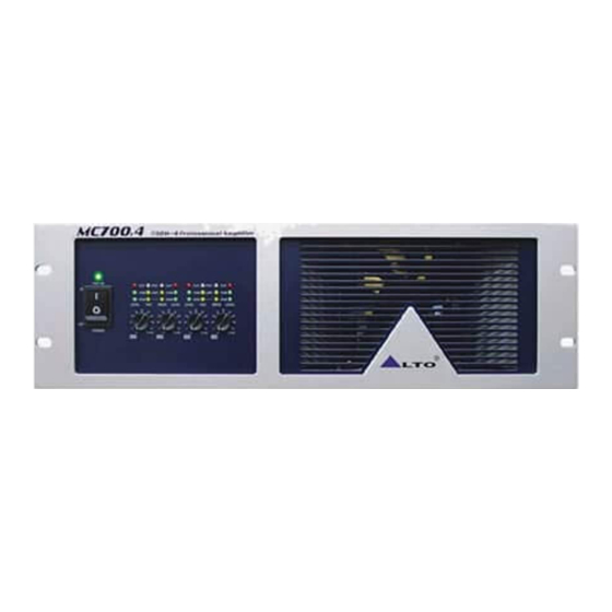
- Page 1 User's Manual MC700.4 FOUR CHANNELS POWER AMPLIFIER www.altoproaudio.com Version 1.0 January 2006 English...
- Page 2 SAFETY RELATED SYMBOLS Fuse To prevent fire and damage to the product, use only the recommended fuse type as indicated in this CAUTION manual. Do not short-circuit the fuse holder. Before RISK OF ELECTRIC SHOCK DO NOT OPEN replacing the fuse, make sure that the product is OFF and disconnected from the AC outlet.
- Page 3 Nothing else to add, but that we would like to thank all the people that made the MC700.4 four channels Power...
-
Page 4: Table Of Contents
TABLE OF CONTENTS 1. INTRODUC ION ..............................4 2. FEATURES................................4 3. CONTROL ELEMENTS............................. 5 4. INSTALLATION..............................APPLICATION............................... CAUTION FOR APPLICATION..........................BLOCK DIAGRAM............................... TECHNICAL SPECIFICATIONS.......................... WARRANTY................................. -
Page 5: Introduc Ion T
This amplifier guarantees total reliability and a trouble-free use even in the most demanding conditions. We believe the MC700.4 not only look great, but provide a perfect performance, what you get is unprecedented performance at an incredibly attractive price. -
Page 6: Control Elements
(dB) (dB) (dB) Power Switch It switches on / off MC700.4 main power. Power LED This LED lights up when the amplifier is powered on Input Level Indicator Display There are three high accurate LED indicators, which shows the level of the input signal. When the respective channel's output signal distortion exceeds 0.5%, the red LED (clip) indicator lights up. -
Page 7: Stereo Mode
3.2 The Rear Panel Apparaten skall anslutas till jordat uttag nar den ansluts till ett natverk BRIDGE BREAKER MONO MODEL SERIAL BRIDGE MONO 1 2 3 4 5 6 7 8 9 10 1 2 3 4 5 6 7 8 9 10 AC INPUT CH3 MODE SWITCHES Ch4 CH1 MODE SWITCHES CH2... -
Page 8: Bridge Mode
BRIDGE MODE 1 2 3 4 5 6 7 8 910 Please refer to chapter 5 for the connection of loads in detain. - function selector Clip limit : set these small dip switches of 1(ON) and 10(ON) at "ON" position , then the clip limit of channel 1 and channel 2 has been working;... -
Page 9: Installation
The MC700.4 professional power amplifier fits into one standard 19" rack unit of space. Be sure that there is enough air space around the unit for sufficient ventilation. If heat release is inadequate, this unit will retain heat inside, which may cause the protection, or even a fire. - Page 10 5.2 Operate MC700.4 Power Amplifier In Parallel Mode In this mode, the channel 1 input signal will be output from the output connectors of both channel 1 and channel 2. The channel 2 input jack is not used. The channel 1 and channel 2 volumes can be adjusted independently.
-
Page 11: Caution For Application
The output capacity of MC 700.4 power amplifier is very high. Be sure to use a speaker system that has sufficient input capacity. If the input capacity of your speaker system is lower than the rated output of the MC700.4 power amplifier, you can protect your speakers by connecting a fuse serially between the speaker and the amplifier as shown below. -
Page 12: Block Diagram
7. BLOCK DIAGRAM 7. BLOCK DIAGRAM... -
Page 13: Technical Specifications
8. TECHNICAL SPECIFICATION Model MC700.4 Output Power 20Hz 20kHz @0.1%THD , stereo Mode 8 ohms per channel (EIAJ) 4x460W 4x750W 4 ohms per channel (EIAJ) Bridge Mono Mode 2 1450W 8 ohms, 1kHz, 0.1% THD (EIAJ) <0.05% Distortion (SMPTE-IM) 20Hz- 20kHz 1dB, -3dB point: 10Hz- 60kHz Frequency Response >300@8 ohms... -
Page 14: Warranty
9. WARRANTY 1. WARRANTY REGISTRATION CARD To obtain Warranty Service, the buyer should first fill out and return the enclosed Warranty Registration Card within 10 days of the Purchase Date. All the information presented in this Warranty Registration Card gives the manufacturer a better understanding of the sales status, so as to purport a more effective and efficient after-sales warranty service. - Page 15 No. 1, Lane 17, Sec. 2, Han Shi West Road, Taichung 40151, Taiwan http://www.altoproaudio.com Tel: 886-4-22313737 email: alto@altoproaudio.com Fax: 886-4-22346757 All rights reserved to ALTO. All features and content might be changed without prior notice. Any photocopy, translation, or reproduction of part of this manual without written permission is forbidden. Copyright 2005 SEIKAKU GROUP NF02316-1.0...
Need help?
Do you have a question about the MC700.4 and is the answer not in the manual?
Questions and answers