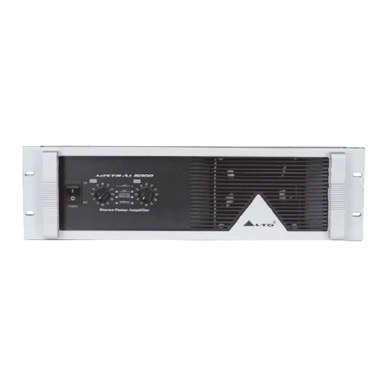
Summary of Contents for Alto 6000
- Page 1 User's Manual MISTRAL6000 STEREO POWER AMPLIFIER www.altoproaudio.com Version 1.0 April 2005 English...
-
Page 2: Safety Related Symbols
CAUTION RISK OF ELECTRIC SHOCK DO NOT OPEN The symbol is used to indicate that some hazard- ous live terminals are involved within this apparatus, even under the normal operating conditions. The symbol is used in the service documentation to indicate that a specific component shall be only replaced by the component specified in that docu- mentation for safety reasons. - Page 3 Preface Dear Customer: Thanks for choosing LTO MISTRAL-6000 Stereo Power Amplifier and thanks for choosing one of The results of AUDIO TEAM job and researches. For our LTO AUDIO TEAM, music and sound are more than a job ...are first of all passion and let us say...our obsession! We have been designing professional audio products for a long time in cooperation with some of the major brands in the world in the audio field.
-
Page 4: Table Of Contents
TABLE OF CONTENTS 1. INTRODUCTION... 2. FEATURES ..4 3. CONTROL ELEMENTS 3.1 The Front Panel 3.2 The Rear Panel 4. APPLICATION 4.1 Stereo Mode 4.2 Bridge Mode 5. TECHNICAL SPECIFICATIONS 6. WARRANTY ..4 ...5 ...8 ...11 ...12... -
Page 5: Features
MISTRAL is a line of high power, low profile, professional Power Amplifiers with advanced features and great reliability. They deliver tremendous power in only two rack spaces, providing high level performance under the most demanding conditions. An automatic speed fan matches cooling capacity with heat requirements. The amplifier frame contains all solid-state circuitry, using complementary silicon output devices. -
Page 6: Control Elements
CONTROL ELEMENTS 3.1 Front Panel Power Switch Turn the unit power on or off. Clip Led When the signal distortion reaches or surpasses 0.5%, the Led lights up. This means the output level of signal source is too high and it is time to reduce input level until clip led turning off. Output Limiter Led While the unit is limiting the output signal, the Led lighting up. -
Page 7: Rear Panel
- Stereo In this mode, Channel 1 and Channel 2 operate independently ( just as traditional stereo amplifier). The signal input into channel 1 can be output from channel 1 only, similarly, the signal input into channel 2 can be output from channel 2 only. -
Page 8: Application
4.1 Stereo Mode In this mode, Channel 1 and Channel 2 operate independently ( just as traditional stereo amplifier). The signal input into channel 1 can be output from channel 1 only, similarly, the signal input into channel 2 can be output from channel 2 only. - Page 9 You can also operate the paralleled mode via outside wiring, so, the signal input from channel 1 or 2 will be output from both channel 1 and 2 simultaneously. The volume of channel 1 or channel 2 can be controlled separately. Input Connector INPUT INPUT...
- Page 10 Input Connector Balanced INPUT INPUT INPUT TIP/PIN 2 TIP/PIN 2 RING/PIN 3 RING/PIN 3 SLEEVE/PIN 1 SLEEVE/PIN 1 TIDE MODE PARALLEL PARALLEL STEREO BALANCED BALANCED BRIDGE OUTPUT OUTPUT INPUT INPUT MODE Release this button Input Connector Balanced INPUT INPUT INPUT TIP/PIN 2 TIP/PIN 2 RING/PIN 3...
-
Page 11: Bridge Mode
In this mode, the signal input into channel 1 will be output from the bridged end, on other hand, the output level control of channel 2 should be turn down to smallest (turn the volume control at counterclockwise). control of channel 1 is used to control the volume of whole system. Input Connector INPUT INPUT... -
Page 12: Technical Specifications
MODEL 20Hz 20KHz@0.1%THD, Stereo Mode 8 ohms per channel(EIAJ) 4 ohms per channel(EIAJ) Bridge Mono Mode 8 ohms, 1KHz, 0.1%THD(EIAJ) Distortion (SMPTE-IM) Frequency Response Damping Factor, 1 kHz and below Signal to Noise,20Hz-20KHz Voltage Gain Input Sensitivity @ 4 ohms Input Clipping Input Impedance Controls... -
Page 13: Warranty Registration Card
1. WARRANTY REGISTRATION CARD To obtain Warranty Service, the buyer should first fill out and return the enclosed Warranty Registration Card within 10 days of the Purchase Date. All the information presented in this Warranty Registration Card gives the manufacturer a better understanding of the sales status, so as to purport a more effective and efficient after-sales warranty service. - Page 14 SEIKAKU TECHNICAL GROUP LIMITED SEKAKU ELECTRON INDUSTRY (H.K.) CO., LTD. No. 1, Lane 17, Sec. 2, Han Shi West Road, Taichung 40151, Taiwan http://www.altoproaudio.com Tel: 886-4-22313737 email: alto@altoproaudio.com Fax: 886-4-22346757 All rights reserved to ALTO. All features and content might be changed without prior notice.


Need help?
Do you have a question about the 6000 and is the answer not in the manual?
Questions and answers