
Related Manuals for Alto Mini-Tube


Summary of Contents for Alto Mini-Tube
- Page 1 User's Manual MINI-TUBE MONO TUBE PREAMP www.altoproaudio.com Version 1.0 August 2004 English...
- Page 2 SAFETY RELATED SYMBOLS External Connection CAUTION Always use proper ready-made insulated RISK OF ELECTRIC SHOCK mains cabling (power cord). Failure to do DO NOT OPEN so could result in shock/death or fire. If This symbol, wherever used, alerts in doubt, seek advice, from a registered you to the presence of un-insulated electrician.
- Page 3 Do not install this product near any direct heat source. Do not block areas of ventilation. Failure to do so could result in fire. Keep product away from naked flames. IMPORTANT SAFETY INSTRUCTIONS Read these instructions Follow all instructions Keep these instructions. Do not discard. Heed all warnings.
- Page 4 Our Mini-Tube Mono Preamplifier is the result of many hours of listening and tests involving common people, area experts, musicians and technicians. The result of this effort is a half rack space unit, the heart of which is an extremely low-noise microphone pre-amp circuit that uses discrete components to produce a highly transparent sound.
-
Page 5: Table Of Contents
4. INSTALLATION & CONNECTION..............8 4.1 Mains Connection 4.2 Audio Connection a. Wiring Configuration b. In Line Connection 4.3 Rack Mounting 5. APPLICATIONS....................9 5.1 The Mini-Tube as icrophone reamplifier 5.2 The Mini-Tube as Direct-Injection ox (DI Box) 5.3 The Mini-Tube evel ranslator 6. -
Page 6: Introduction
LTO Mini-Tube meets highest and no-compromise requirements in terms of operation, sound, specifications and workmanship. LTO Mini-Tube is a half rack space unit, the heart of the MINI-TUBE is an extremely low-noise microphone pre-amp circuit that uses discrete components such as 12AX7WA... -
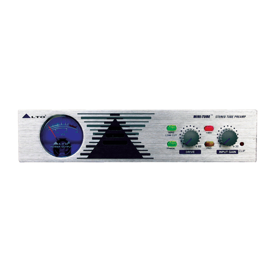
Page 7: Guidepost Of The Front Panel
A 20dB Pad is designed to attenuate the incoming signal level to provide increased "headroom" for the operator. Gain Control (6): This control sets the amount of boost to the signal being processed by this pre- amplifier. Use this control to adapt the Mini-Tube to either home recording level... -
Page 8: The Rear Panel
MODEL SERIAL BALANCED UNBALANCED BALANCED UNBALANCED a. Power Supply Connection Please use the 18VAC AC/AC Adaptor provided by LTO to connect your Mini- Tube. Detail your can follow the illustration. 18VAC POWER MODEL SERIAL 18VAC b. Analogue Inputs / Outputs The output XLR connector is servo balanced and operates at +4dBu. -
Page 9: Installation & Connection
4. INSTALLATION & CONNECTION 4.1 Mains Connection - Please ensure that the LTO Mini-Tube Preamplifier is connected to the correct supply voltage before operating this unit. - Only use the 18VAC AC/AC Adaptor provided by LTO. 4.2 Audio onnection LTO Mini-Tube Preamp presents with balanced XLR connectors and 1/4"... -
Page 10: Rack Mounting
The most secure mounting is on a "universal" rack shelf, available from various rack manufacturers or your music dealer. The Mini-Tube Preamplifier's height conforms to single-space mounting, and up to two Mini-Tube Preamplifier may be mounted side-by-side in a standard universal EIA 19" equipment rack. -
Page 11: The Mini-Tube As A Direct-Injection Ox (Di Box) B
Simply connect the line output of your instrument to the XLR or 1/4" TRS Input jack on the rear panel of Mini-Tube , then use the Mini-Tube's balanced output to send the signal to the next stage. 5.3 The... -
Page 12: Technical Specifications
6. TECHNICAL SPECIFICATIONS 6.1 Block Diagram... -
Page 13: Specifications
6.2 Specifications Preamp Bandwidth 20Hz ~ 50KHz / 2dB General Number of Channels THD+Noise 0.05% @ GAIN +0dBu (A-Weighting) Performance Output Level (MAX) +22dBu -88dBu( 2dBu) Noise Floor Signal to Noise >108dBu Input Connectors XLR and 1/4" Input Impedance, XLR 1.3K Ohms Input Impedance, Hight Z 1/4 1Meg Ohms... -
Page 14: Warranty
7. WARRANTY 7.1 Warranty registration card To obtain Warranty Service, the buyer should first fill out and return the enclosed Warranty Registration Card within 10 days of the Purchase Date. All the information presented in this Warranty Registration Card gives the manu- facturer a better understanding of the sales status, so as to purport a more effective and efficient after-sales warranty service. - Page 15 e. In no event shall be liable for any incidental or consequential damages. Some states do not allow the exclusion or limitation of incidental or consequential damages, so the above exclusion or limitation may not apply to you. f. This warranty gives you the specific rights, and these rights are compatible with the state laws, you may also have other statutory rights that may vary from state to state.
- Page 16 SEKAKU ELECTRON INDUSTRY (H.K.) CO. LTD No. 1, Lane 17, Sec. 2, Han Shi West Road, Taichung, 401 Taiwan http://www.altoproaudio.com Tel: 886-4-22313737 email: alto@altoproaudio.com Fax: 886-4-22346757 All rights reserved to ALTO. All features and content might be changed without prior notice. Any photocopy, translation, or reproduction of part of this manual without written permission is forbidden.
Need help?
Do you have a question about the Mini-Tube and is the answer not in the manual?
Questions and answers