Table of Contents
Advertisement
Advertisement
Table of Contents

Related Manuals for Kinder Camber


Summary of Contents for Kinder Camber
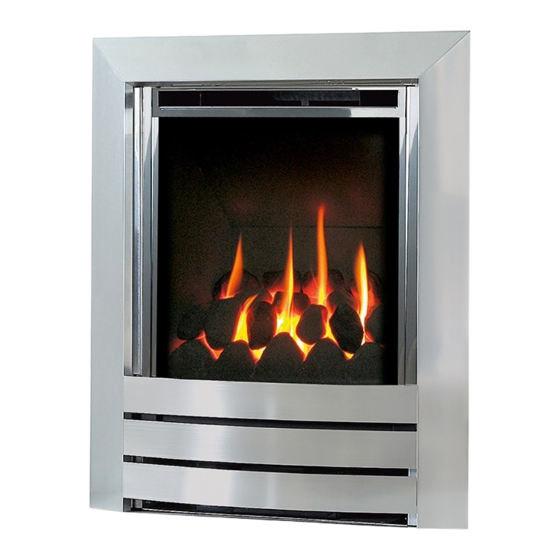
- Page 1 Camber DECORATIVE PEBBLE FUEL EFFECT GAS FIRE Installation and Maintenance Instructions Hand these instructions to the user Model No’s KRDP**MN are for use on Natural Gas (G20) at a supply pressure of 20 mbar in G.B. / I.E. ** denotes fascia / colour variant...
-
Page 2: Table Of Contents
CONTENTS Section 1 Information and Requirements PAGE Appliance Information Conditions of Installation Flue and chimney suitability Fireplace / surround suitability Shelf position Chimney inspection Fire place opening / catchment space Precast Flues Metal Flue boxes Hearths 1.10 Spillage Monitoring System Section 2 Installation of Fire Unpacking the fire... -
Page 3: Information And Requirements
20.0 +/-1.0 mbar Ignition : Push-button Piezo Electrode Spark Gap 4.5mm Packed Weight (without fender) 15 kg Fire box Dimensions (with camber trim fitted) Width : (with camber trim, no spacer) 520mm Height : (with camber trim, no spacer) 610mm... -
Page 4: Conditions Of Installation
INSTALLATION REQUIREMENTS CONDITIONS OF INSTALLATION It is the law that all gas appliances are installed only by a CORGI Registered Installer, in accordance with these installation instructions and the Gas Safety (Installation and Use) Regulations 1998 as amended. Failure to install appliances correctly could lead to prosecution. -
Page 5: Fireplace / Surround Suitability
FIREPLACE / SURROUND SUITABILITY The fire must only be installed on a hearth it must not be installed directly onto carpet or other combustible floor materials. The fire is suitable for fitting to non-combustible fire place surrounds and propri- etary fire place surrounds with a temperature rating of at least 150 o c. If a heating appliance is fitted directly against a wall without the use of a fire surround or fire place all combustible material must be removed from behind the trim. -
Page 6: Fire Place Opening / Catchment Space
There must be no leakage of smoke through the structure of the chimney during or after the smoke pellet test and it is important to check inside upstairs rooms adjacent to the chimney / flue. Check the chimney pot / terminal and general condition of the brickwork or masonry. - Page 7 Table A - Installation Depth Requirements for a Kinder Camber being installed into a brick built chimney, requiring 12.0 litres of debris collection volume (fig. 2). When installing this product into a builders opening / brick-built chimney, the depth required is a minimum of 170mm. The 12.0 litres of debris collection volume is achieved by the space available taper down the sides of the firebox.
-
Page 8: Precast Flues
1.7 FITTING TO PRE-CAST FLUE INSTALLATIONS When installing this appliance into pre-cast flues, always ensure that the spigot restrictor baffle has been removed. To install the fire box in to pre-cast flue starter blocks, there must be at least 170mm from the mounting face of the fire to the rear of the pre-cast flue starter block to allow sufficient space for debris collection. -
Page 9: Spillage Monitoring System
1.10 SPILLAGE MONITORING SYSTEM This appliance is fitted with an atmosphere sensing spillage monitoring system in the form of an oxygen sensing pilot. This is designed to shut the fire off in the event of a partial or complete blockage of the flue causing a build up of combus- tion products in the room in which the fire is operated. -
Page 10: Installation Of Fire
1off Loose items bag. 1off Cable Fixing Kit 1off Camber trim 1off each User instruction book and Installation book 1off Camber Ashpan INSTALLING THE FIRE BOX Establish which type of flue you are intending to install the fire in to :-... - Page 11 Proceed as follows :- Remove the Camber trim. Remove the burner heat shield from the front of the fire box to allow access to the burner. See fig. 3 below. Fig. 3 Ensure that the hearth is protected from damage and carefully lift the fire box into the fire opening, then slide it back into position.
- Page 12 Whilst the fire box is still in position, decide which side the gas supply is to enter the fire from. If concealed pipe work is required plan the pipe run to enter the fire box through one of the openings in the sides of the fire box below the fuelbed support panel and connect to the isolating / inlet elbow.
- Page 13 IMPORTANT : Sealing of the Gas Unused Gas Pipe Inlet Apertures In line with current CORGI regulations, it is imperative that the gas supply inlet apertures that are not utilised during the installation are sealed with the foil tape as supplied. Failure to seal these inlet apertures could lead to flame reversal, which in turn will damage the burner and control systems of the product.
- Page 14 The preferred method of fixing which is suitable for almost all situations is the cable fixing method which is described in the following section in detail. If the 50mm black spacer is used, the fire may be secured using the cable method as described below, or alternatively, in installations where the cable method is not suitable (eg.
- Page 15 Position the fire carefully on the (protected) surface of the hearth and reach into the fire opening. Thread each of the cables vertically downwards through the pair of fixing eyes on the same side of the fire. Thread the free end of the cables through the corresponding circular hole on each side of the lower rear of the fire.
- Page 16 Refit the front burner heat shield to the sides of the fire box (2 Screws) and secure the camber trim to the fire using the magnets provided. Before making the final gas connection, thoroughly purge the gas supply pipework to remove all foreign matter, otherwise serious damage may be caused to the gas control valve on the fire.
-
Page 17: Gas Tightness And Burner Pressure
GAS TIGHTNESS AND INLET PRESSURE Remove the pressure test point screw from the inlet elbow and fit a manometer. Turn on the main gas supply and carry out a gas tightness test. Depress the control knob and turn anti-clockwise to the position marked pilot. - Page 18 Position front ceramic rail on burner front ceramic support and ensure that the locating channel in the front ceramic rail is correctly located onto the lip on the burner front ceramic support. (See fig. 11 below) Fig. 11 Pick pebbles A to E and arrange along the the front rail, ensuring that they are evenly spaced.
- Page 19 Select pebbles F to I and arrange behind the front row of pebbles, ensuring that flame paths as indicated below are not interupted. (See fig. 13 below) Fig. 13 Pebble H Pebble F Pebble I Pebble G Select pebbles K, L & M and arrange along the rear of the fuelbed, using the ribs in the rear of the fuelbed as a guide for placement.
- Page 20 The exact position and fit of the pebbles may be finely adjusted to give the most pleasing and random appearance. Warning : Use only the pebbles supplied with the fire. When replacing the pebbles remove the old pebbles and discard them. Fit a complete set of pebbles of the correct type.
-
Page 21: Lighting The Appliance
LIGHTING THE APPLIANCE Turn on the gas isolation tap. Depress the control knob and turn anti-clockwise to the position marked pilot. Hold in the control knob for a few seconds to purge the pipe work. Continue to hold-in the control knob and press the igniter button. If the burner does not light, continue to press the igniter button until ignition occurs. - Page 22 If spillage persists, the flue is not functioning correctly and a fault exists. If, after investigation the fault cannot be traced and rectified, the fire must be disconnected from the gas supply and expert advice obtained. If there is an extractor fan fitted any where in the vicinity of the appliance, the spillage test should be repeated with the fan running on maximum and all interconnecting doors open.
-
Page 23: Maintenance
Prepare work area (lay down dust sheets etc.) 4.1.2 Lift the Camber trim and ash pan cover out of the way and put them in a safe location. Remove the loose pebbles from the fuel bed and front ceramic rail. Remove the front ceramic from the rail. Unscrew the two pozi-driv fixing screws which secure the burner heat shield and remove it from the fire. - Page 24 Removing the Control Tap from the fire. 4.3.1 Remove the burner assembly as in section 4.1. 4.3.2 Pull the control knob off the control tap spindle. 4.3.3 Loosen and remove the three gas pipe retaining nuts from the control tap and release the ends of the gas pipes from the control tap body. Loosen and remove the thermocouple securing nut from the end of the control tap.
- Page 28 B-39030 Manual Gas Valve (NG) B-102880 This appliance must only be used with the Camber trim and ashpan supplied Due to our policy of continual improvement and development the exact accuracy of illustrations and descriptions contained in this book cannot be guarantee Part No.
Need help?
Do you have a question about the Camber and is the answer not in the manual?
Questions and answers