Table of Contents
Advertisement
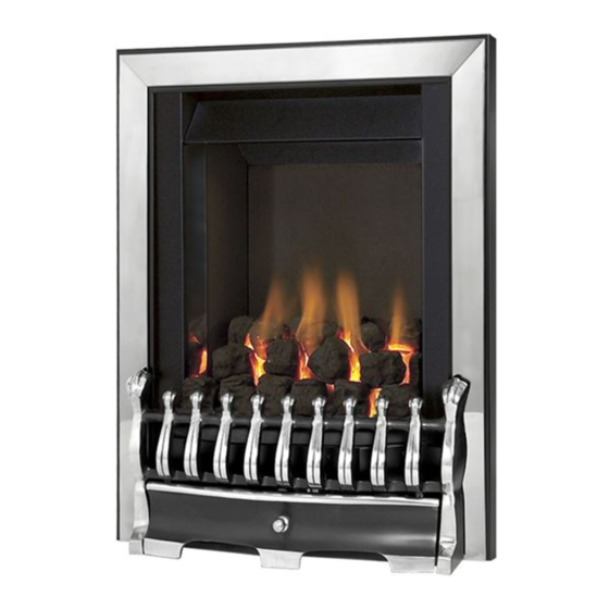
Kalahari SC
Powerflue
DECORATIVE FUEL EFFECT
POWERFLUE GAS FIRES
Installation and Maintenance Instructions
Hand these instructions to the user
Model No. KPFC00SN is for use on Natural Gas (G20) at a supply
pressure of 20 mbar in G.B. / I.E.
Model No. KPFC00SP is for use on Propane Gas (G31) at a supply
pressure of 37 mbar in G.B. / I.E.
Advertisement
Table of Contents

Subscribe to Our Youtube Channel
Related Manuals for Kinder Kalahari SC Powerflue


Summary of Contents for Kinder Kalahari SC Powerflue
- Page 1 Kalahari SC Powerflue DECORATIVE FUEL EFFECT POWERFLUE GAS FIRES Installation and Maintenance Instructions Hand these instructions to the user Model No. KPFC00SN is for use on Natural Gas (G20) at a supply pressure of 20 mbar in G.B. / I.E. Model No.
-
Page 2: Table Of Contents
CONTENTS Section 1 Information and Requirements PAGE Appliance Information Conditions of Installation Flue Terminal Position Fireplace / Surround Suitability Fireplace Opening Shelf Position Installation Types Hearths Spillage Monitoring System Section 2 Installation of Fire Unpacking the fire Marking the Firebox Recess Fitting the Fan Unit / Firebox 12-20 Making the Electrical Connection... -
Page 3: Information And Requirements
SECTION 1 INFORMATION AND REQUIREMENTS APPLIANCE INFORMATION Model KPFC00SN KPFC00SP Gas Type Main injectors (2 off) Size 260 Size 85 Pilot Type Copreci Copreci Single Flame Single Flame 21100 / 162 21100 / 167 Max. Gross Heat Input : 6.9 kW Min. -
Page 4: Conditions Of Installation
INSTALLATION REQUIREMENTS CONDITIONS OF INSTALLATION It is the law that all gas appliances are installed in accordance with the rules in force only by a CORGI Registered Installer in G.B, in accordance with these installation instructions and the Gas Safety (Installation and Use) Regulations 1998 as amended. -
Page 5: Flue Terminal Position
FLUE TERMINAL POSITION The minimum acceptable dimensions from the flue terminal to obstructions and ventilation openings are shown below in fig. 1 and listed in the table (Fig. 2 below) IT IS IMPORTANT THAT THE POSITION OF THE FLUE ALLOWS THE FREE PASSAGE OF AIR ACROSS IT AT ALL TIMES. -
Page 6: Fireplace / Surround Suitability
FIREPLACE / SURROUND SUITABILITY The fire must only be installed on a hearth it must not be installed directly onto carpet or other combustible floor materials. The fire is suitable for fitting to non-combustible fire place surrounds and propri- etary fire place surrounds with a temperature rating of at least 150 o c. If a heating appliance is fitted directly against a wall without the use of a fire surround or fire place all combustible material must be removed from behind the trim. -
Page 7: Installation Types
INSTALLATION TYPES This fire can be fitted against an outside facing facing flat wall surface or into a fireplace opening cut into the wall. When fitting the fire in front of the inner cavity wall, the distance between the mounting face of the fire and the rear face of the firebox (170mm nominally), a false chimney breast or fireplace surround should be constructed. - Page 8 Fig. 5 The Interactive Zone - Openings, beams or joists within this area need to be assessed. 400mm interactive area 600mm load The Load Triangle - No triangle Beam or opening permissible in this area Lintel e.g. 750mm x 75mm Firebox recess in wall Opening Height 550mm Minimum...
-
Page 9: Hearths
Remove any combustible material from within the area of the opening. No combustible material can be allowed to come into contact with any area of the appliance. Fig. 7 Lintel must project Opening Sizes Width :- Minimum 150mm each 375mm Minimum side of opening 440mm Maximum Opening Sizes Height... -
Page 10: Spillage Monitoring System
SPILLAGE MONITORING SYSTEM This appliance is fitted with an atmosphere sensing spillage monitoring system in the form of an oxygen sensing pilot. This is designed to shut the fire off in the event of a partial or complete blockage of the flue pipe causing a build up of combustion products in the room in which the fire is operated. -
Page 11: Installation Of Fire
SECTION 2 INSTALLATION OF FIRE UNPACKING THE FIRE Carefully lift the fire out of the carton. Remove the loose item packaging carefully from the front of the appliance. Check the contents as listed :- Packing Check List 1off Fire box / burner assembly 1off Boxed fuelbed base, ceramic front rail and 18 synthetic coals 1off... -
Page 12: Fitting The Fan Unit / Firebox
FITTING THE FAN UNIT / FIREBOX Remove the 7 outer case fixing screws which hold the fan unit cover in place. See fig. 9 below. Fig. 9 7 off Outer Case Fixing Screws Remove the fan mounting plate from the main body of the fan unit by removing the four screws from the fan unit as indicated below in fig. - Page 13 When the fan mounting plate screws have been removed, slide the fan mounting plate cover over the wiring harness and mains cable as shown below in fig. 11, taking care not to damage the wiring harness / cables Fig. 11 Screw the fan mounting plate you have just removed centrally about the hole drilled in the outer cavity wall, using the 4 screws and rawplugs provided.
- Page 14 Screw the flue pipe & gasket to the rear of the firebox using the 4 off screws provided. See fig. 13 below. Fig. 13 Flue pipe secured with four screws Locate the fire into the fireplace opening / surround and locate the flue pipe into the fan mounting plate as shown on the previous page in Fig.
- Page 15 Remove the fire from the fireplace opening and remove any burrs from the cut edge of the flue pipe. Proceed as follows to remove the burner assembly from the firebox :- Remove the trim. Remove the burner heat shield from the front of the fire box to allow access to the burner, as shown below in fig.
- Page 16 Fig. 16 Unscrew the burner assembly fixing screws at either side of the firebox, and the two fixing screws at the base of the fire (See fig. 17 below). Carefully pull the base of the burner forwards from the fuel-bed support panel.
- Page 17 Whilst the fire box is still in position, decide which side the gas supply is to enter the fire from. If concealed pipe work is required plan the pipe run to enter the fire box through one of the openings in the sides of the fire box below the fuelbed support panel and connect to the isolating / inlet elbow.
- Page 18 Depending on whether the spacer option has been selected, (50mm black spacer) there is a choice of methods of fixing the firebox which are provided to enable the installer to deal with any type of installation. The preferred method of fixing which is suitable for almost all situations is the cable fixing method which is described in the following section in detail.
- Page 19 hole on each side of the lower rear of the fire. Carefully slide the fire box back into the fire opening and pull both cables tight. Thread a tensioning screw over each of the cables and ensure that the tensioning nut is screwed fully up against the hexagon shoulder of the tensioning screw (this provides maximum travel for the tensioning nut).
- Page 20 Before making the final gas connection, thoroughly purge the gas supply pipework to remove all foreign matter, otherwise serious damage may be caused to the gas control valve on the fire. The other firebox fixing method is as follows :- In installations where the cable method is not suitable (e.g.
-
Page 21: 2.4 Making The Electrical Connection
2.4 MAKING THE ELECTRICAL CONNECTION WARNING : THIS APPLIANCE MUST BE EARTHED AND SHOULD BE PREFERABLY CONNECTED VIA A 3 AMP FIXED FUSED SPUR WITH A MINIMUM CONTACT SEPARATION OF 3MM. IT MAY HOWEVER BE CONNECTED TO A 3 PIN PLUG TO BS 5733, THAT IS FITTED WITH A 3 AMP FUSE TO BS 1362. -
Page 22: Making The Solenoid / Wiring Loom Connection
Any cut-outs in the rear panel not used must be sealed with the length of foil tape supplied in the loose items pack Fig. 23 Grommet Earth Wire to be secured to rear panel of firebox Wiring Loom Connection (Solenoid to Fan Unit) 2.7 FINAL FITTING OF THE FAN UNIT Fit the flue spigot ring over the flue pipe, and then insert the circular rope... - Page 23 Fig. 25 Fig. 26 Fan unit secured to fan mounting plate with 1 off screw in each corner as shown below Refit the fan unit cover with the seven screws as removed in fig. 10 on page 12. Seal any gaps in the brickwork to prevent moisture ingress. Do not under any circumstances block any ventilation openings in the fan unit cover.
-
Page 24: Gas Tightness & Inlet Pressure
Check the pressure test point screw for gas tightness with the appliance turned on using a suitable leak detection fluid or detector. SECTION 3A ASSEMBLING FUEL BED AND COMMISSIONING - KINDER KALAHARI MODELS SUPPLIED WITH PEBBLE PACK AS EXTRA COST OPTION 3.1A... - Page 25 Position front ceramic rail on burner front ceramic support and ensure that the locating channel in the front ceramic rail is correctly located onto the lip on the burner front ceramic support. (See fig. 28 below) Fig. 28 Pick pebbles A to E and arrange along the the front rail, ensuring that they are evenly spaced.
- Page 26 Select pebbles F to I and arrange behind the front row of pebbles, ensuring that flame paths as indicated below are not interupted. (See fig. 30 below) Fig. 30 Pebble H Pebble F Pebble I Pebble G Select pebbles K, L & M and arrange along the rear of the fuelbed, using the ribs in the rear of the fuelbed as a guide for placement.
- Page 27 The exact position and fit of the pebbles may be finely adjusted to give the most pleasing and random appearance. Warning : Use only the pebbles supplied with the fire. When replacing the pebbles remove the old pebbles and discard them. Fit a complete set of pebbles of the correct type.
-
Page 28: B Assembling The Ceramics And Fuel Bed (Coal Fuelbed)
SECTION 3B ASSEMBLING FUEL BED AND COMMISSIONING - KINDER KALAHARI (COAL FUELBED MODELS) 3.1B ASSEMBLING THE CERAMICS AND FUEL BED NOTE : The position of the fuel-bed components are critical to the performance of the product. Therefore please ensure that the fuel-bed components are positioned as described in the following section prior to requesting a service call due to soot build up, poor flame pattern etc. - Page 29 Fit five of the large sized coals onto the front ceramic rail, ensuring that they are evenly spaced. Use the recess’s in the front ceramic rail as a guide for placement. (See fig. 34 below) Fig. 34 Select four of the large coals and arrange behind the front row of coals, ensuring that flame paths as indicated below are not interupted.
- Page 30 Select three of the large coals and arrange along the rear of the fuelbed, using the ribs in the rear of the fuelbed as a guide for placement. (See fig. 36 below) Fig. 36 Select the two small coals and position to fill the gaps at each end of the third row of coals, as shown.
- Page 31 Select the remaining four coals and position along the rear edge of the fuelbed (See fig. 38 below) Fig. 38 The exact position and fit of the coals may be finely adjusted to give the most pleasing and random appearance. Warning : Use only the coals supplied with the fire.
-
Page 32: Lighting The Appliance
LIGHTING THE APPLIANCE Switch on the mains supply at the fixed fused spur. Turn on the gas isolation tap, which can be found at the back of the firebox. Depress the control lever fully downwards to the position marked “Z” Hold down the control lever for a few seconds to allow the gas to reach the pilot. -
Page 33: Checking For Clearance Of Combustion
CHECKING FOR CLEARANCE OF COMBUSTION PRODUCTS Close all doors and windows in the room. Light the fire and allow to run for approximately 5 minutes on high position. After approximately 5 minutes hold a smoke match just inside and below the centre of the lower front edge of the top of the fire. (It is recommended that a suitable smoke match holder is used when check ing for clearance of combustion products). -
Page 34: Maintenance
Servicing Notes Servicing should be carried out annually by a competent person such as a CORGI registered engineer. This is a condition of the Kinder Fires extended guarantee schemes. The service should include visually checking the chimney and fire opening for accumulations of debris and a smoke test to check for a positive up-draught in the chimney. -
Page 35: Removal Of The Battery Ignitor
It is now necessary to refit and correctly tension the operating cable. To do this, first set the control lever to the horizontal (central position), this is the position which creates maximum tension in the operating cable. Refit the operating cable to the aluminium operating arm, firstly locating the nipple on one end of the cable into recess in operating arm and then feed the other end through hole in operating arm. -
Page 36: Replacement Of The Control Cable
Note : Prior to replacing the oxypilot on this product due to suspected failure of the component, please remove all debris that has collected on the lint guard of the oxypilot itself. Replacing the Control Cable 4.5.1 The control lever operating cable can be seen running across the base of the fire, below the burner. -
Page 37: Parts Shortlist
4.5.5 Fit the hexagonal control lever cable locking bush onto the control lever and fit the control cable loosely into the bush in the gap between the two lengths of p.t.f.e. sleeve. Ensure that the cable is located in the retaining hole in the locking bush and tighten the screw sufficiently to retain the cable but still allowing it to slide for adjustment. -
Page 40: Bfm Europe Ltd
Due to our policy of continual improvement and development the exact accuracy of illustrations and descriptions contained in this book cannot be guaranteed Part No. B-77480 Issue 3 BFM Europe Ltd. Trentham Lakes Stoke-on-Trent Staffordshire ST4 4TJ Telephone - General Enquiries : (01782) 339000 Telephone - Service : (0844) 7700169...
Need help?
Do you have a question about the Kalahari SC Powerflue and is the answer not in the manual?
Questions and answers