Table of Contents
Advertisement
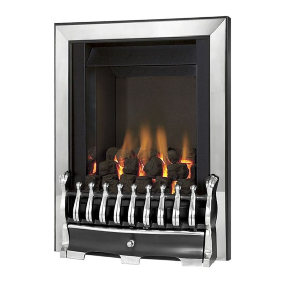
Kalahari
DECORATIVE FUEL EFFECT GAS FIRE
Installation and Maintenance Instructions
Hand these instructions to the user
Model No's KRDC00MN and KRDC00SN are for use on Natural Gas
(G20) at a supply pressure of 20 mbar in G.B. / I.E.
Model No's KRDC00MP and KRDC00SP are for use on Propane Gas
(G31) at a supply pressure of 37 mbar in G.B. / I.E.
Advertisement
Table of Contents

Related Manuals for Kinder Kalahari


Summary of Contents for Kinder Kalahari
- Page 1 Kalahari DECORATIVE FUEL EFFECT GAS FIRE Installation and Maintenance Instructions Hand these instructions to the user Model No’s KRDC00MN and KRDC00SN are for use on Natural Gas (G20) at a supply pressure of 20 mbar in G.B. / I.E. Model No’s KRDC00MP and KRDC00SP are for use on Propane Gas...
-
Page 2: Table Of Contents
CONTENTS Section 1 Information and Requirements PAGE Appliance Information Conditions of Installation Flue and chimney suitability Fireplace / surround suitability Shelf position Chimney inspection Fire place opening / catchment space Fitting to Metal Flue Boxes Pre-Cast Flues Hearths 1.10 Spillage Monitoring System Section 2 Installation of Fire Unpacking the fire... -
Page 3: Information And Requirements
SECTION 1 INFORMATION AND REQUIREMENTS APPLIANCE INFORMATION Model KRDC00MN (MC) KRDC00MP (MC) KRDC00SN (SC) KRDC00SP (SC) Gas Type Main injectors (2 off) Size 260 Size 85 Pilot Type Copreci Copreci 21100 / 141 (MC) 21100 / 264 (MC) 21100 / 162 (SC) 21100 / 263 (SC) Max. -
Page 4: Conditions Of Installation
INSTALLATION REQUIREMENTS CONDITIONS OF INSTALLATION It is the law that all gas appliances are installed only by a GAS SAFE Registered Installer, in accordance with these installation instructions and the Gas Safety (Installation and Use) Regulations 1998 as amended. Failure to install appliances correctly could lead to prosecution. -
Page 5: Fireplace / Surround Suitability
FIREPLACE / SURROUND SUITABILITY The fire must only be installed on a hearth it must not be installed directly onto carpet or other combustible floor materials. The fire is suitable for fitting to non-combustible fire place surrounds and proprietary fire place surrounds with a temperature rating of at least 150 o c. If a heating appliance is fitted directly against a wall without the use of a fire surround or fire place all combustible material must be removed from behind the trim. -
Page 6: Fire Place Opening / Catchment Space
There must be no leakage of smoke through the structure of the chimney during or after the smoke pellet test and it is important to check inside upstairs rooms adjacent to the chimney / flue. Check the chimney pot / terminal and general condition of the brickwork or masonry. - Page 7 Table A - Installation Depth Requirements for a Kinder Kalahari being installed into a brick built chimney, requiring 12.0 litres of debris collection volume (fig. 2) When installing this product into a builders opening / brick-built chimney, the depth required is a minimum of 170mm. The 12.0 litres of debris collection volume is achieved by the space available taper down the sides of the firebox.
-
Page 8: Fitting To Metal Flue Boxes
120mm or the fire surround may be packed away from the wall using suitable non-combustible board, providing the installation is correctly sealed. If in doubt about the suitability of the fire contact Kinder Fires for advice before proceeding. This fire has been designed to fit standard 100mm pre-cast starter blocks with 3 inch rebated surrounds. -
Page 9: Spillage Monitoring System
1.10 SPILLAGE MONITORING SYSTEM This appliance is fitted with an atmosphere sensing spillage monitoring system in the form of an oxygen sensing pilot. This is designed to shut the fire off in the event of a partial or complete blockage of the flue causing a build up of combus- tion products in the room in which the fire is operated. -
Page 10: Installation Of Fire
SECTION 2 INSTALLATION OF FIRE UNPACKING THE FIRE Carefully lift the fire out of the carton. Remove the loose item packaging carefully from the front of the appliance. Check the contents as listed :- Packing Check List 1off Fire box / burner assembly 1off Boxed ceramic base, front ceramic rail and 18 coals (16 large, 2 small) coals... - Page 11 For manual control models proceed as follows :- Remove the trim / fret. Remove the burner heat shield from the front of the fire box to allow access to the burner. See fig. 3 below. Fig. 3 Ensure that the hearth is protected from damage and carefully lift the fire box into the fire opening, then slide it back into position.
- Page 12 For Slide Control Models Proceed as follows: Remove the trim / fret. Remove the burner heat shield from the front of the fire box to allow access to the burner. See fig. 5 below. Fig. 5 Ensure that the hearth is protected from damage and carefully lift the fire box into the fire opening, then slide it back into position.
- Page 13 Fig. 6 Unscrew the burner assembly fixing screws at either side of the firebox, and the two fixing screws at the base of the fire (See fig. 6 above). Carefully pull the base of the burner forwards from the fuel-bed support panel.
- Page 14 Continue for all models Whilst the fire box is still in position, decide which side the gas supply is to enter the fire from. If concealed pipe work is required plan the pipe run to enter the fire box through one of the openings in the sides of the fire box below the fuelbed support panel and connect to the isolating / inlet elbow.
- Page 15 IMPORTANT : Sealing of the Gas Unused Gas Pipe Inlet Apertures In line with current GAS SAFE regulations, it is imperative that the gas supply inlet apertures that are not utilised during the installation are sealed with the foil tape as supplied. Failure to seal these inlet apertures could lead to flame reversal, which in turn will damage the burner and control systems of the product.
- Page 16 The preferred method of fixing which is suitable for almost all situations is the cable fixing method which is described in the following section in detail. If the 2 inch black spacer is used, the fire may be secured using the cable method as described below, or alternatively, in installations where the cable method is not suitable (eg.
- Page 17 Thread a tensioning screw over each of the cables and ensure that the tensioning nut is screwed fully up against the hexagon shoulder of the tensioning screw (this provides maximum travel for the tensioning nut). Fit a screwed nipple on to each of the cables and pull hand tight up against the tensioning screw, then secure each nipple with a flat bladed screwdriver.
- Page 18 This should not be overtightened. Move the control lever fully downwards and check that the left hand micro-switch operates the igniter and that the control valve spindle is fully depressed. Move the control lever upwards to the “off” position and check that the right hand (cut-off) micro-switch operates.
-
Page 19: Gas Tightness And Inlet Pressure (Mc Models)
GAS TIGHTNESS AND INLET PRESSURE (MANUAL CONTROL MODELS) Remove the pressure test point screw from the inlet elbow and fit a manometer. Turn on the main gas supply and carry out a gas tightness test. Depress the control knob and turn anti-clockwise to the position marked pilot. -
Page 20: Assembling Fuel Bed And Commissioning
SECTION 3 ASSEMBLING FUEL BED AND COMMISSIONING ASSEMBLING THE CERAMICS AND FUEL BED NOTE : The position of the fuel-bed components are critical to the performance of the product. Therefore please ensure that the fuel-bed components are positioned as described in the following section prior to requesting a service call due to soot build up, poor flame pattern etc. - Page 21 Fit five of the large sized coals onto the front ceramic rail, ensuring that they are evenly spaced. Use the recess’s in the front ceramic rail as a guide for placement. (See fig. 15 below) Fig. 15 Select four of the large coals and arrange behind the front row of coals, ensuring that flame paths as indicated below are not interupted.
- Page 22 Select three of the large coals and arrange along the rear of the fuelbed, using the ribs in the rear of the fuelbed as a guide for placement. (See fig. 17 below) Fig. 17 Select the two small coals and position to fill the gaps at each end of the third row of coals, as shown.
- Page 23 Select the remaining four coals and position along the rear edge of the fuelbed Fig. 19 The exact position and fit of the coals may be finely adjusted to give the most pleasing and random appearance. Warning : Use only the coals supplied with the fire. When replacing the coals remove the old coals and discard them.
-
Page 24: Lighting The Appliance (Manual Control Model)
LIGHTING THE APPLIANCE (Manual Control Models) Turn on the gas isolation tap. Depress the control knob and turn anti-clockwise to the position marked pilot. Hold in the control knob for a few seconds to purge the pipe work. Continue to hold-in the control knob and press the igniter button. If the burner does not light, continue to press the igniter button until ignition occurs. -
Page 25: Checking For Clearance Of Combustion Products
The gas control can be moved from the High to Low position to give the desired heat output and the flame control adjusted to give the most pleasing flame effect or maximum glow. To turn the fire off, FULLY raise the control lever to the OFF position. WARNING : If the fire goes out for any reason or is turned off and it isnecessary to re-light the fire it is important to allow the fire to cool for 3 minutes before attempting to re-light it. -
Page 26: Maintenance
Servicing Notes Servicing should be carried out annually by a competent person such as a GAS SAFE registered engineer. This is a condition of the Kinder Fires extended guarantee schemes. The service should include visually checking the chimney and fire opening for accumulations of debris and a smoke test to check for a positive up-draught in the chimney. -
Page 27: Removal Of The Control Tap
Removing the Control Tap from the fire. 4.3.1 Remove the burner assembly as in section 4.1. 4.3.2 Pull the control knob off the control tap spindle. 4.3.3 Loosen and remove the three gas pipe retaining nuts from the control tap and release the ends of the gas pipes from the control tap body. Loosen and remove the thermocouple securing nut from the end of the control tap. -
Page 28: Removal Of The Battery Ignitor
the two pozi-drive fixing screws which secure the burner heat shield and remove it from the fire. 4.5.3 Isolate the gas supply and remove the inlet pipe from the appliance inlet elbow. To allow burner removal, the control lever operating cable must be removed. -
Page 29: Removing The Oxy-Pilot Assembly
4.7.2 Replace in the reverse order using a 1.5V AA Alkaline Battery. Removing the Oxy-Pilot Assembly Note: Because this appliance is fitted with an atmosphere sensing ‘Oxy- Pilot’ it is not possible to replace the thermocouple separately, because the thermocouple position is factory set to a tight tolerance. Any replacement of parts on the pilot requires a complete new pilot assembly. - Page 30 4.9.2 Hold the hexagonal control lever cable locking bush with a spanner and unscrew the locking screw using a 2mm allen key to release the cable from the control lever. The control cable can now be removed from the cable guide tubes. 4.9.3 To fit the replacement cable, thread the end of the new cable into the long length of p.t.f.e.
-
Page 31: Parts Shortlist
FRET INFORMATION To enable Customers to choose their own style of fret these fires are now available without frets. In order to maintain the efficient and safe operation of the fire it is important that any fret which is used must comply with the following dimensions. (Fig. - Page 32 Due to our policy of continual improvement and development the exact accuracy of illustrations and descriptions contained in this book cannot be guaranteed Part No. B-103550 Issue 4 BFM Europe Ltd. Trentham Lakes Stoke-on-Trent Staffordshire ST4 4TJ www.bfm-europe.com Telephone - General Enquiries : (01782) 339000 Telephone - Service : (0844) 7700169...
Need help?
Do you have a question about the Kalahari and is the answer not in the manual?
Questions and answers