
Related Manuals for Walker Bay Genesis Console 310


Summary of Contents for Walker Bay Genesis Console 310
- Page 1 ASSEMBLING INSTRUCTIONS Genesis Console 310 & 340 For Customer Service or Technical Support visit www.walkerbay.com...
-
Page 2: Introduction
Genesis Console RIB or as a scaled down Light Genesis Console runabout/ tender. This package provides the fi rst fully integrated injection molded center console to the market, and is designed specifi cally for Walker Bay’s award winning Genesis line. -
Page 3: Table Of Contents
CONTENTS Introduction ............2 Boating Safety Signs & Symbols ......4 Completed Boats ..........5 925100 Basic Console Kit ....... 6 - 12 Steering Wheel ..........7 Console and Seat ......... 7 - 12 925180 Electrial/Lighting Kit ....... 13 Side Lights ............14 Switch Panel ............. -
Page 4: Boating Safety Signs & Symbols
BOATING SAFETY SIGNS AND SYMBOLS This is the safety alert symbol. It is used to alert you to potential personal injury hazards. Obey all safety messages that follow this symbol to avoid possible injury or death. DANGER Indicates an imminently hazardous situation which, if not avoided, will result in death or serious injury or substantial property damage. -
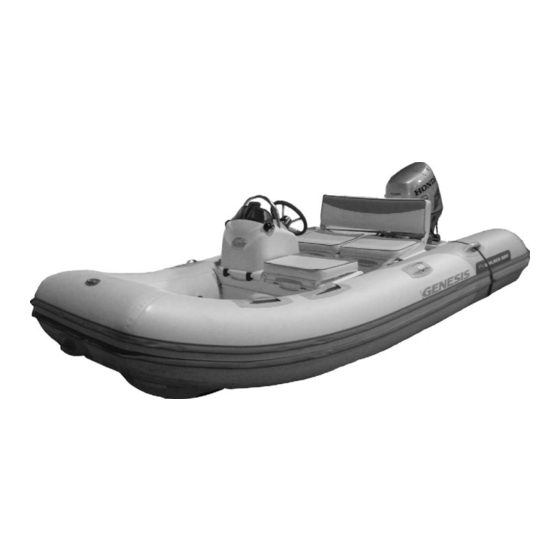
Page 5: Completed Boats
Completed Boats: Front View: Left View: Right View:... -
Page 6: 925100 Basic Console Kit
(steering, electrical, fuel, etc.) and have tested the functioning of them. Also cover the cables with the white cable sheathing provided. Pushing and locking down the seats should be the fi nal step of assembling. If you have any questions during assembling, call Walker Bay at 1-888-44 WALKER. - Page 7 STEP ONE: INSTALLING THE STEERING WHEEL 2. Install the steering wheel cap by fi rstly loosen- 1. Remove the nut and washer from the steering ing the small bolt on the side of the steering wheel shaft, slide the steering wheel down on the shaft, housing with a small fl...
- Page 8 3. Insert the ratchet clip adapter into the seat 4. Push the adapter all the way up until it sits patches from below. The pull strap should face fi rmly inside the seat patch. Repeat this with the down and the opening of the adapter should face other adapter, also with the strap facing down.
- Page 9 CAUTION Do not lock down the console until you are satisfi ed with the set-up of the entire boat. Complete the installation of all other controls, gauges, cables and wires fi rst. The seat racheting system is designed to hold the seat fi rmly in place. It could be diffi cult to remove it from the tube once locked down.
- Page 10 14. Open the seat lid, and look for the two 13. The next step is to further secure the seat rounded spots at the center of the bottom of the box to the fl oor. Look for the 2 sets of drywall seat box.
- Page 11 17. The completed lock-down screws. Do 18. If you are not installing the Deluxe Seat & Cushion exactly the same with another set of screws Kit, you can install the original Genesis seat on the at the other spot. 2nd set of seat patches. 19.
-
Page 12: Fuel Tank
MUST NOT place the fuel tank inside the lower seat box under the console. According to marine safety regulations, the battery and the fuel tank must be separated. Walker Bay recommends that the fuel tank to be placed under the rear seat, if you install the Genesis seat there.
Need help?
Do you have a question about the Genesis Console 310 and is the answer not in the manual?
Questions and answers