Table of Contents
Advertisement
Quick Links
Advertisement
Table of Contents

Related Manuals for Clear-Com SB-704


Summary of Contents for Clear-Com SB-704
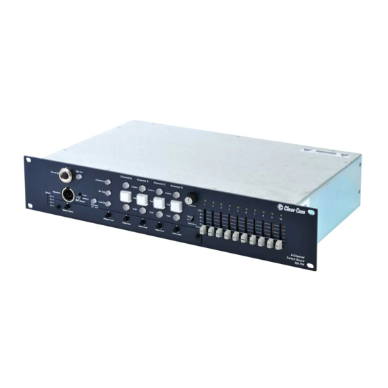
- Page 1 CLEAR-COM ENCORE SB-704 MAIN STATION I N S T R U C T I O N M A N U A L...
- Page 2 All Rights Reserved Clear-Com, the Clear-Com logo, and Clear-Com Concert are trademarks or registered trademarks of HM Electronics, Inc. The software described in this document is furnished under a license agreement and may be used only in accordance with the terms of the agreement.
-
Page 3: Table Of Contents
The Clear-Com Concept........ - Page 4 SB-704 Block Diagram ........
-
Page 5: Important Safety Instructions
IMPORTANT SAFETY INSTRUCTIONS 1. Read these instructions. 2. Keep these instructions. 3. Heed all warnings. 4. Follow all instructions. 5. Do not use this apparatus near water. 6. Clean only with dry cloth. Please read and follow 7. Do not block any ventilation openings. Install in accordance with the these instructions before manufacturer’s instructions. - Page 6 Figure 1: Safety Symbols EMC AND SAFETY The SB-704 station meets all relevant CE, FCC, UL, and CSA specifications set out below: EN55103-1 Electromagnetic compatibility. Product family standard for audio, video, audio-visual, and entertainment lighting control apparatus for professional use.
-
Page 7: Operation
We recommend that you read through this manual completely to better understand the functions of the SB-704. If you encounter a situation or have a question that this manual does not address, contact your dealer or call Clear-Com directly. -
Page 8: Description
The following is a list of features found in the SB-704 intercom station: • MICROPROCESSOR CONTROL: Most aspects of station operation are under microprocessor control. - Page 9 ASSIGNMENT MATRIX: Up to ten stations or groups of stations can be assigned to any one of the four intercom lines. • LINK FUNCTION: The SB-704 has a link function that places all four channels into a common party line at the single push of a button. •...
-
Page 10: Normal Operation
NORMAL OPERATION Once installed and operational, the SB-704 is easy to operate. The following sections describe normal operation of the unit, use of controls available under the access panel, and abnormal operation of the power distribution system. -
Page 11: Listening To Intercom Channels
½ second, depending upon whether there was a single or multiple short or overload. The other channels continue to operate normally. The SB-704’s advanced fail-safe circuit will bring the power back up even under full load conditions. Front-panel lights indicate a fault on any of the four channels. -
Page 12: Sending And Receiving Call Signals
The main program input is the one on the XLR connector on the rear panel. To listen to the main program in the speaker or headphone, adjust the program level control just below the link and all talk pushbuttons. Sending and Receiving Call Signals To send a call signal on an intercom channel press the call button for that channel. -
Page 13: Remote Mic Kill Function
Those needing to communicate can then set their talk functions to on as needed. Note: The remote mic kill button only functions if the SB-704 main station is powering all of the stations in the system. Pressing the button momentarily interrupts power to the other beltpacks and stations in the system. -
Page 14: Hidden Adjustment Controls
• TALK LATCH DISABLE: Four DIP switches (one for each channel) disable the latching action of the selected channel. • PROGRAM ON/OFF: Four DIP switches (one for each channel) enable feeding the main program input to the selected intercom channel. The main program input is the one on the XLR-3F on the rear panel. -
Page 15: Rear Panel Options
Note: If the link function is to be used on an SB-704 and there is more than one main station in the system, it can only be used on the unit that provides termination. -
Page 16: Summary Of Main Front-Panel Keys, Lights, And Controls
intercom line and break it apart in several places while it is plugged into the station to isolate the section of line that is shorted. SUMMARY OF MAIN FRONT-PANEL KEYS, LIGHTS, AND CONTROLS Table 1 summarizes the meaning of various front-panel keys, lights, and controls. - Page 17 Function (Continued) “On” State “Off” State Momentary or Latching All-Talk Key (press to send Amber Momentary only microphone’s audio to all channels) Link-On Key (press to link all Amber Latching only channels together so that station operates as one party line) Remote Microphone Kill Key Amber Momentary only...
- Page 18 1 - 1 2 S B - 7 0 4 M A I N S T A T I O N...
-
Page 19: Installation
USING THE LINK FUNCTION The link function in the SB-704 uses relays to connect the four party lines together. In doing so, it also removes the terminations from channels B, C, and D such that the new party line on channel A has only one termination when... -
Page 20: Fail-Safe Power
If there is more than one SB-704 or MS-704 in a system, the link function can only be used at the station where the terminations are set on. FAIL-SAFE POWER An intercom power supply has special needs that are not met by traditionally designed power supplies. - Page 21 • CONNECTION TO AC MAINS: The AC power line supplies power to the SB-704’s internal power supply. The power supply will accept any line voltage between 100 and 240 VAC at 50-60 Hz. It will automatically adjust to the line voltage. There is no need for a voltage selector switch or an external fuse.
-
Page 22: Intercom Cable Considerations
SB-704. The single-channel remote stations are connected to the ten switched intercom connectors. These connectors derive their DC power internally from the SB-704. The station comes set from the factory with the power on the assigned lines #1 - #5 connected to channel A's power. The power for channels #6 - #10 is sourced from channel B. -
Page 23: Portable Installation Cable
Portable Installation Cable Practical cable for portable system interconnections is flexible, two-conductor, shielded microphone cable. We suggest you use Belden #1800F (24 gauge). For runs longer than 500 ft. (152.5 m) use a 20 gauge cable or larger (Belden #8412). Permanent Installation Cable Vinyl-jacketed shielded pair is the cable of choice for permanent installations. - Page 24 Figure 2-4: Interconnect Cable Detail Note: The remote stations connected to each channel are powered from the intercom cable for that channel. In the case above, a short on any one line will only take that channel down. 2 - 6 S B - 7 0 4 M A I N S T A T I O N...
-
Page 25: Physical Installation
Figure 2-5: Typical Mixed System Wiring PHYSICAL INSTALLATION You can install the SB-704 in a standard equipment rack, or you can use it as stand-alone unit sitting on a table or desk. For installing in an equipment rack, the unit requires 3.5 in. (8.89 cm or 2RU) of rack space. The stations are10.5 in. -
Page 26: Intercom Line Connectors (Rear Panel)
3. If desired, set the set screw on top of the bushing to lock the mic in place. INTERCOM LINE CONNECTORS (REAR PANEL) The SB-704 has a single male XLR-3 connector for each intercom line. The ten switched intercom lines also have male XLR-3 connectors. The pinout of the intercom connectors is as follows:... -
Page 27: Ifb/Hot Mic (Rear Panel, 1/4-Inch Phone Jack)
A ¼ in. (0.64 cm) phone jack marked IFB/hot Mic provides an output signal from the selected microphone. This output is also intended to work with Clear-Com’s IFB system. Consult the factory for installation instructions. The jack connections are as follows:... -
Page 28: Auxiliary Program Inputs
Figure 2-6: Accessory Connector DB-15F - Rear View Auxiliary Program Inputs Four different program inputs, one for each channel, are provided. These auxiliary program inputs can only be fed directly to their associated intercom line. The only controls that affect these inputs are the PGM level controls associated with each channel and the internal program interrupt switch which is active if the function has been activated with an option DIP switch and a talk is active on that channel. -
Page 29: Internal Option Jumpers
INTERNAL OPTION JUMPERS There are several jumper options inside the chassis of the SB-704. To access these options remove the top cover of the unit. Note: Remove AC power from the unit before removing the top cover. Note: This adjustment should only be carried out by qualified service personnel. -
Page 30: Power Source Selection For Switchable Intercom Lines
announce output and replaces it with audio from the selected panel or headset microphone. The factory default position for J11 is in the off position, blocking program audio feed from the announce output. POWER SOURCE SELECTION FOR SWITCH- ABLE INTERCOM LINES The power pins (pin #2) of the ten switchable intercom connectors are connected together in two groups of five. - Page 31 2 - 1 3 S B - 7 0 4 M A I N S T A T I O N...
- Page 32 2 - 1 4 S B - 7 0 4 M A I N S T A T I O N...
-
Page 33: Maintenance
SB-704 BLOCK DIAGRAM 3 - 1 S B - 7 0 4 M A I N S T A T I O N... - Page 34 Figure 3-8: SB-704 Block Diagram 3 - 2 S B - 7 0 4 M A I N S T A T I O N...
-
Page 35: Technical Specifications
TECHNICAL SPECIFICATIONS SB-704 MAIN STATION dBu is an absolute measurement. 0 dBu is referenced to 0.775 volts RMS Panel Microphone Input Input Type Electret Input Impedance >=2KΩ Mic Limiter Threshold 0dBu ±3dB Mic Limiter Range >= 15dB Headset Microphone Input... - Page 36 Output Impedance >= 200Ω Load Impedance >= 600Ω IFB/Hot Mic Type Unbalanced Output Impedance 150Ω Load Impedance >= 600Ω Frequency Response Panel Mic - Party Line 600 - 10KHz ± 3dB Headset Mic - Party Line 200 - 12KHz ± 3dB Headset Mic - Line Out 200 - 12KHz ±...
-
Page 37: Mains Power
Min Gain Panel Mic - Party Line <= 25dB Mains Power Input Voltage Range 100 - 240 VAC Input Frequency Range 50 - 60 Hz Input Power <= 60 VAC Output Voltage 30 VDC ± 0.5V Output Current per Channel (Continuous) 1.2 A Output Current per Channel (Peak) 2 A (Do not exceed the 1.2A rating... - Page 38 Weight 10.93 lbs. (4.97 kg) Notice About Specifications While Clear-Com makes every attempt to maintain the accuracy of the information contained in its product manuals, that information is subject to change without notice. Performance specifications included in this manual are design-center specifications and are included for customer guidance and to facilitate system installation.
-
Page 39: Limited Warranty
LIMITED WARRANTY Clear-Com warrants that at the time of purchase, the equipment supplied complies with any specification in the order confirmation when used under normal conditions, and is free from defects in workmanship and materials during the warranty period. Clear-Com offers 24 x 7... -
Page 40: Warranty Repairs And Returns
Tel: +1 510 337 6600 Email: customerservicesUS@vitecgroup.com Asia Pacific & South America Tel: +1 510 337 6600 Email: customerservicesAPAC@vitecgroup.com Clear-Com has the right to inspect the equipment and/or installation or relevant packaging. W A R R A N T Y... -
Page 41: Non-Warranty Repairs And Returns
1-year or 90-day warranty. SERVICE CONTRACT Clear-Com also offers service contracts that provide 24 x 7 telephone support, advance replacements, training, proactive maintenance, on-site visits, and no charge for repair or replacement of equipment. For more information, contact your authorized dealer, distributor, or sales representative. - Page 42 BE DEFECTIVE WITHIN THE WARRANTY PERIOD AS AFORESAID. This warranty does not cover any damage to a product resulting from cause other than part defect and malfunction. The Clear-Com warranty does not cover any defect, malfunction, or failure caused beyond the control of...
Need help?
Do you have a question about the SB-704 and is the answer not in the manual?
Questions and answers