Table of Contents
Advertisement
Advertisement
Table of Contents

Related Manuals for Clear-Com ICS-2003


Summary of Contents for Clear-Com ICS-2003
- Page 1 ICS-2003 INTERCOM STATION I N S T R U C T I O N M A N U A L...
- Page 2 U.S.A Clear-Com is a registered trademark of Vitec Group Communications, Inc. The Clear-Com Logo is a registered trademark of Vitec Group Communications, Inc. Eclipse is a registered trademark of Vitec Group Communications, Inc. Windows is a registered trademark of Microsoft Corp.
-
Page 3: Table Of Contents
CONTENTS IMPORTANT SAFETY INSTRUCTIONS OPERATION Introduction ..........1-1 Description . - Page 4 I C S - 2 0 0 3 I N T E R C O M S T A T I O N...
-
Page 5: Important Safety Instructions
Please read and follow these this manual. instructions before operating (3) Do not install an ICS-2003 intercom station near a heat source such as a an ICS-2003 intercom radiator, heat register, stove, or other apparatus (including amplifiers) that produces heat. Do not place naked flame sources such as candles on or near an station. - Page 6 CAUTION RISK OF ELECTRIC SHOCK DO NOT OPEN This symbol alerts you to the presence of uninsulated dangerous voltage within the product's enclosure that might be of sufficient magnitude to constitute a risk of electric shock. Do not open the product's case. This symbol informs you that important operating and main- tenance instructions are included in the literature accompanying this product.
-
Page 7: Operation
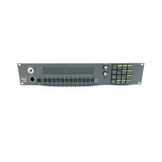
OPERATION INTRODUCTION This chapter describes how to operate an ICS-2003 display intercom station and its digital equivalent, the ICS-2003T. Station operators can use this manual after the Eclipse System has been correctly installed and configured. DESCRIPTION This chapter describes how... - Page 8 This section describes the front-panel controls and indicators. These include: • The display screen • Intercom and program controls • Talk/listen selectors and indicators • “Answer Back” facility • Keypad buttons Figure 2 illustrates the ICS-2003/ICS-2003T front-panel controls and indicators. Panel Mic Connector Intercom Volume LCD Display Headset Connector...
- Page 9 Listen Window The listen window is located directly above the talk window. It contains one listen label per selector. Labels refer to the listen paths that are established when the selector is pushed up. Answer-Back Window The answer-back window is located above the “Answer Back” selector. It displays a list of as many as five incoming calls.
- Page 10 Page Override Page override is a special function in the station in which the intercom volume defaults to a preset to a value when commanded to by the central matrix. Any fixed group can be assigned the page-override function through the configuration program.
- Page 11 Monitoring/Eavesdropping Indicators If any other station begins monitoring a station a beep (the monitoring-alert tone) will sound at the station. To inhibit the monitoring-alert tone, use the configuration program. Call-Waiting Indicator If a station calls another station with a selector programmed with the caller’s label, the red LED will flash rapidly.
- Page 12 Answer-Back Facility The primary function of answer-back facility is to answer or call other stations or interfaces not assigned to a station’s selectors. Stations and interfaces that are assigned to a station’s selectors also can be answered or called with the answer-back facility.
- Page 13 Removing Labels from the Answer-Back Stack Any label will be automatically removed from the stack if it is not answered within a certain time interval, which is set by the answer-back auto-clear time in the configuration program. To manually remove the current caller’s label from the answer-back stack, push up on the “Answer Back”...
- Page 14 Listen-Level Mode To use the listen-level adjust mode: 1. Push (for less than 1 second) and quickly release the “Listen Level” button. 2. “Listen Level Adjust Mode” will appear in the message window to indicate the function is on and the LEDs of all active listen selectors will begin to flash. Note: Only active selectors can be adjusted in listen-level mode.
- Page 15 Keypad: Administrative Buttons The upper portions of 5 of the 12 buttons are labeled with the function active during normal station operation; these functions are: • (3) “Menu” • (5) “Display Listen” Labels • (9) “Swap” window • (*) “Dial” phone •...
- Page 16 View Forced Listens This function displays destinations or sources of forced listens. Use the selectors to select “Destinations” or “Sources.” Viewing destinations displays all stations or interfaces always connected to the station’s out-going audio. Viewing sources displays all stations or interfaces always connected to the station’s incoming audio.
- Page 17 Warning: All station key reassignments take place immediately upon exiting this function. Active talk and listen paths will be disconnected when their labels are removed. System Configuration Menu The System Configuration menu changes some of the Eclipse System configuration parameters typically only available through the configuration program.
- Page 18 Warning: All station selector reassignments take place immediately upon exiting this function. Active talk and listen paths will be disconnected when their labels are removed. Assign Forced Listens To add or remove forced listens: 1. Select “select source -> assign destinations” to choose a single source and assign it to multiple destinations.
- Page 19 Dial Button (*) The “Dial” phone button turns the station keypad into a touch-tone phone keypad, allowing DTMF tones (Touch Tones) to be generated for telephone dialing. To place a telephone call: 1. Push a talk selector assigned to a telephone interface. 2.
- Page 20 PTT status. This input only controls latched talks. Programmable Relay Each ICS-2003 station includes a relay controlled by the system program and independent of the local station function. This relay can be assigned to any label(s) in the system, which will activate whenever a talk or listen is set to that label(s).
-
Page 21: Expansion Panel Operation
Mute Relay The mute relay is activated whenever any talk selector is activated at the station. The mute relay is commonly wired such that whenever it is activated, the volume of the monitor speaker in that room is decreased (muted). OPT-100 Auxiliary Audio Option The OPT-100 Auxiliary Audio option provides the following features: •... - Page 22 label assigned to the key. If the listen and talk labels are the same, then there will be no change. The function will time-out after 10 seconds. 1 - 1 6 I C S - 2 0 0 3 I N T E R C O M S T A T I O N...
-
Page 23: Installation
INSTALLATION INTRODUCTION This chapter describes the installation of the ICS-2003/ICS-2003T display station, including: • Station placement • Wiring • Mains AC power • Adjustments • Configuration • Accessory panels MOUNTING STATIONS Leave at least 2 inches (51mm) of clearance behind... - Page 24 The following sections describe connecting the station to the matrix frame, and all the connections between the station and local devices. Each of the following sections describes cable and station connector wiring: • Analog matrix frame to station wiring • Digital matrix frame to station wiring •...
- Page 25 DIGITAL MATRIX FRAME TO STATION WIRING The ICS-2003T differs from the ICS-2003 because it contains an internal digital audio/data communications module (COM-20) that works in conjunction with the DIG-2 digital interface module to connect digital stations to the matrix. The DIG-2 digital interface module offers two options for wiring the frame to intercom stations.
- Page 26 Note: Ensure that the Select switch on the station’s rear panel is in the correct position for the intended use. Matrix Frame End BNC-16 No Connection (NC) No Connection (NC) Station End No Connection (NC) Pair 1 Multiplexed Data/Audio Multiplexed Data/Audio No Connection (NC) No Connection (NC) No Connection (NC)
- Page 27 feed (program audio) can be heard on the station’s speaker and headset; it cannot be heard by other stations in the Matrix system. To connect an external program feed to the station: 1. Connect the balanced audio pair to pins 1 and 9. 2.
- Page 28 • PTT: Activate Two-Way Radio Keys—implements a push-to-talk function for all two-way radio talk selectors. When the logic input is active, the station operates normally. When the logic input is deactivated, all active two-way radio talk selectors are disabled. Any controls (relays, etc.) assigned to the labels are activated or deactivated along with their assigned labels.
- Page 29 OPT-100 AUXILIARY AUDIO I/O OPTION The OPT-100 Auxiliary Audio option provides the following features: • Hot Mic output • SA audio and relay outputs • Auxiliary audio line level output Figure 7 shows the pinout for the intercom station’s DB-15F Auxiliary Audio I/O connector.
- Page 30 Both normally open and normally closed contacts are provided. They are rated at 1 Amp at 24 VDC. This relay is not designed for switching mains AC line voltage. To switch an external device running on mains AC line voltage, use an external relay (or other switching mechanism) activated by this relay (see Figure 7).
-
Page 31: Mains Ac Power
Front Panel Headset Connector Figure 9: Binaural Headset Wiring MAINS AC POWER The station has a separate, external DC power supply with a removable AC power cord. The power supply is “universal,” operating over a voltage range of 90 to 260 VAC and 45 to 65 Hz. The maximum dissipation is 30 W. A bracket has been provided to mount this external supply if necessary. - Page 32 PANEL MICROPHONE GAIN The preamplifier gain of the panel microphone can be adjusted over a range of 0 to 10 dB; the maximum is the panel microphone gain’s default setting. However, if two stations are talking to each other at the same time with the panel microphone gain set to maximum, feedback may occur even if the speaker mute (see “Speaker Mute”) is set to maximum.
-
Page 33: Configuration
Configuration System Program (see Eclipse Configuration System Manual for more information). Also refer to the Operation chapter for details regarding the configuration options available from the ICS-2003’s menus. ACCESSORY PANELS The following sections describes how to install the following optional, accessory key panels: •... - Page 34 STATION CONNECTION A cable is supplied with each panel to connect it to a station or to additional panels. The cable is 6-ft. long (1.8 m) and has a DB-9F connector on one end and a DB-9M connector on the other end. If custom length cables are to be made, they should be made with 9 conductor control cable with 22 to 24 AWG wire.
-
Page 35: Maintenance
MAINTENANCE INTRODUCTION This chapter provides station microprocessor resetting instructions, maintenance menu use, troubleshooting guidelines, schematics, assembly drawings, and component lists. STATION RESET The station’s microprocessor has a reset button located in an unmarked hole just below the program volume knob on the right side of the unit’s front panel. If the station is acting erratically, try resetting it by performing one of the following: •... - Page 36 • Keypad button functions do not operate, or the station beeps when a button is pressed (affected buttons could include “Assign,” “Station,” “Dial,” “Menu,” and “Swap”). 1. Ensure the function has not been inhibited from the configuration program of the station’s local Configuration menu. 2.
- Page 37 5. Test the integrity of the station’s audio path by temporarily setting a forced ‘ listen to it. 6. Reset the station’s Matrix card in the Matrix frame. 7. Replace the station’s Matrix card in the Matrix frame. 8. Reset the station. 9.
-
Page 38: Technical Reference
TECHNICAL REFERENCE Figure 10: Digital Block Diagram—ICS-2003 Main PCB 3 - 4 I C S - 2 0 0 3 I N T E R C O M S T A T I O N... - Page 39 ----------------------- 710432 - SCH - D - Figure 11: ICS-2003 Main PCB Sheet 1 of 2 Rev. C 3 - 5 I C S - 2 0 0 3 I N T E R C O M S T A T I O N...
- Page 40 Figure 12: Analog Block diagram—ICS-2003 Main PCB This page is a place holder. 3 - 6 I C S - 2 0 0 3 I N T E R C O M S T A T I O N...
- Page 41 ----------------------- 710432 - SCH - D - Figure 13: ICS-2003 Main PCB Sheet 2 of 2 3 - 7 I C S - 2 0 0 3 I N T E R C O M S T A T I O N...
- Page 42 Figure 14: Assembly Drawing—ICS-2003 Main PCB 3 - 8 I C S - 2 0 0 3 I N T E R C O M S T A T I O N...
- Page 43 BILL OF MATERIALS FOR THE ICS-2003/2003T MAIN PCB Capacitors Value Type Volts Tol. Part # Designator Ceramic Disc SMD50 151120 C63 C69 C83 100 pF Ceramic Disc SMD50 151124 C67 C74 220 pF Ceramic Disc SMD50 151128 C32 C38 .0015 uF...
- Page 44 Tantalum SMD 25 151192 C2 C33 C88 C89 C C101 C103 Aluminum SMD50 151200 C34 C43 C45 C55 C57 C64 220 uF Aluminum SMD25 151204 C6 C8 C10 C11 1000 uF Aluminum 150092 C35 C107 C108 2200 uF Aluminum 150120 C7 C9 Resistors &...
- Page 45 4.02K OHM 1/10 411447 R51 R52 R68 4.32K OHM 1/10 411450 R61 R62 4.75K OHM 1/10 411454 R24 R25 R66 R110 8.25K OHM 1/10 411477 9.09K OHM 1/10 411481 R118 10.0K OHM 1/10 411485 R1 R2 R3 R4 R6 R7 R8 R9 R10 R11 R12 R19 R20 R26...
- Page 46 Diodes and Transistors Device Description Part # Designator Diode BAV70 Dual Diode Com Cath 481019 D1 D4 Diode BAV99 Dual Diode Series SMD 481033 D2 D3 D5 D6 D7 D8 D9 D10 D11 Transistor 2222A NPN 40V 600ma SMD 481026 Q7 Q8 Q9 Transistor 2907A PNP 60V 600ma SMD...
- Page 47 Micro. P 68LC302 Micro Cont SMD 481049 ROM Mem. EPROM ASSY, ODD, ICS-2003 710430 ROM Mem. EPROM ASSY, EVEN, ICS-2003 710431 IC11 Regulator 7705 Supply Supervisor SMD 481018 RAM Mem. 62256 CMOS SRAM 32K X 8 481047 IC3 IC7 IC10 IC12 Video Cont.
- Page 48 ----------------------- 710433 - SCH - D - Figure 15: Schematic—ICS-2003 Front Panel PCB Rev. B 3 - 1 4 I C S - 2 0 0 3 I N T E R C O M S T A T I O N...
- Page 49 Figure 16: Assembly Drawing—ICS-2003 Front Panel PCB Rev. B 3 - 1 5 I C S - 2 0 0 3 I N T E R C O M S T A T I O N...
- Page 50 BILL OF MATERIALS FOR THE ICS-2003/2003T FRONT PANEL PCB CAPACITORS Value Type Volts Tol. Part # Designator Ceramic Disc SMD50 151172 C2 C3 C4 C5 C6 C7 C8 C9 C10 C11 C12 Tantalum SMD 16 151185 Tantalum SMD 25 151192 Resistors &...
- Page 51 DIODES AND TRANSISTORS Device Description Part # Designator Diode BAV70 Dual, Com. Cath. SOT23 481019 Red 5ma LED SMD 0805 391001 D1 D3 D5 D7 D9 D11 D13 D15 D17 D19 D21 D23 D25 Green 5ma SMD 0805 391002 D2 D4 D6 D8 D10 D12 D14 D16 D18...
- Page 52 GND2 12 VCC1 VCC2 VCC3 GND1 5 VCC4 Figure 17: COM-10 Communications Module Schematic Rev. A 3 - 1 8 I C S - 2 0 0 3 I N T E R C O M S T A T I O N...
- Page 53 Figure 18: Assembly Drawing - COM-10 Communications Module Rev. A BILL OF MATERIALS FOR THE ICS-2003/ICS-2003T COM-10 PCB CAPACITORS Value Type Volts Tol. Part # Designator Tantalum 150032 Monolithic 150035 .0022 uF Mylar 150045 RESISTORS & RESISTOR PACKS Value Power Type Tol.
- Page 54 Figure 19: Schematic—OPT-100 (Aux Audio Option) Rev. A 3 - 2 0 I C S - 2 0 0 3 I N T E R C O M S T A T I O N...
- Page 55 Figure 20: Assembly Drawing—OPT-100 Module Rev. A BILL OF MATERIALS FOR THE OPT-100 PCB Resistors & Resistor Packs Value Power Type Tol. Part # Designator OHM 1/4 Carbon Film 410010 R1 R2 R3 R4 R5 R6 4.7K OHM 1/4 Carbon Film 410013 OHM 1/4 Carbon Film...
- Page 56 3 - 2 2 I C S - 2 0 0 3 I N T E R C O M S T A T I O N...
- Page 57 Sync on falling edge of GPIO0. (Interrupt Mask=1, Mute is off, Gain (G(3..0)) is 8 (+12dB), Attenuation (A(4..0)) is 9 (-13.5dB), Mute=0, DO1=0, ADV=1, DI1=1.) GPIO0 J.E.Galbraith DATE 04-07-99 fi CLEAR-COM SPCLK DATE DSP/CODEC DATE INTERCOM SYSTEMS SPMOSI A2 A1...
- Page 58 TP46 TP27 TP12 TP14 TP29 TP25 TP24 AGND TP23 TP22 FCL2 CLEAR-COM FCL3 COPYRIGHT (C) 1999 TP18 R25 R26 C15 R27 COM-20 ASSY# 710435 Figure 22: Assembly Drawing—COM-20 Communication PCB Rev. C BILL OF MATERIALS FOR COM-20 COMMUNICATION PCB CAPACITORS...
- Page 59 Tantalum SMD 25V 151192 C19 C24 C25 100 uF Aluminum 150155 RESISTORS Value Power Type Tol. Part # Designator OHM 1/10 411100 R16 R22 R34 R35 R36 R40 R75 OHM 1/10 411181 47.5 OHM 1/10 411262 OHM 1/10 411326 R46 R47 R48 R49 R50 R51 R52 R53 OHM 1/10...
- Page 60 Miscellaneous Device Description Part # Designator Connector JUMP JAX 210103 Connector 210112 JP1(2) HEADER MULTI PIN HEADER((PER)PIN) Connector 210188 15 PIN (M) RT ANG PC MTG D TYPE CON Connector DUAL ROW HEADER 17 POS. .230IN 210279 Connector 210335 J2 RJ-45 RT ANG MOD CON 1-PORT SHIELDED Connector 210354...
- Page 61 3 - 2 7 I C S - 2 0 0 3 I N T E R C O M S T A T I O N...
-
Page 62: Specifications
SPECIFICATIONS Note: 0 dBv is referenced to 0.775 V RMS FRONT-PANEL CONTROLS AND CONNECTORS Talk/Listen Switches: Function Buttons Answer Back Switch Volume Controls Headset Connector 1 D4M XLR Panel Mic Connector 1 1/4 in. Phone Jack REAR-PANEL CONNECTORS Miscellaneous DB-15F To Matrix RJ-45 &... - Page 63 HEADPHONE OUTPUTS Impedance 50 to 600 Ohms Power 1/2 W into 50 Ohms SPEAKER AMPLIFIER OUTPUT Impedance 8 Ohms Power LINE INPUT (2-PAIR LISTEN FROM MATRIX) Type Transformer Balanced Impedance 8k Ohms Bridging Level 0 dBv nominal Freq. Resp. 100 Hz to 15 kHz +/- 2 dB LINE OUTPUT (2-PAIR TALK TO MATRIX) Type Transformer Balanced...
- Page 64 AC MAINS POWER Voltage 117 VAC nominal (105 to 130 VAC) 220 VAC nominal (200 to 240 VAC) AC Current 0.2 Amp at 117 VAC 0.1 Amp at 220 VAC Frequency 45 to 65 Hz TEMPERATURE Operating between 0 and 50 C (32 to 125 F) Storage between 0 and 70 C (32 to 150 F) HUMIDITY...
- Page 65 4 - 4 I C S - 2 0 0 3 I N T E R C O M S T A T I O N...
-
Page 66: Vitec Group Communications Warranty
TECHNICAL SUPPORT Clear-Com offers 24/7 customer support. To ensure complete and timely support to its customers, VGC maintains Technical Service Centers (TSC) staffed by qualified technical personnel. A... -
Page 67: Warranty Repairs
WARRANTY REPAIRS While VGC will ensure complete system integrity by providing whatever support is necessary to resolve any failure covered under the terms of the warranty, the normal procedure will be to repair or replace any defective Line Replaceable Unit (LRU) that is returned to VGC during the warranty period. - Page 68 hereunder and/or with respect to any non-conformance or defect in any such product and/or part thereof delivered hereunder and/or with respect to any non-conformance or defect in any such product and/or part thereof delivered hereunder, or any other warranties or guarantees, including but not limited to any liability of VGC for any consequential and/or incidental damages and/or losses (including loss of use, revenue, and/or profits).
- Page 69 WARRANTY VALIDATION To validate your warranty, fill in the information below, and mail it to your local Technical Service Center. 5 - 4 V I T E C G R O U P C O M M U N I C A T I O N S W A R R A N T Y...
Need help?
Do you have a question about the ICS-2003 and is the answer not in the manual?
Questions and answers