Table of Contents
Advertisement
Quick Links
Advertisement
Table of Contents

Related Manuals for METREL MI 3250


Summary of Contents for METREL MI 3250
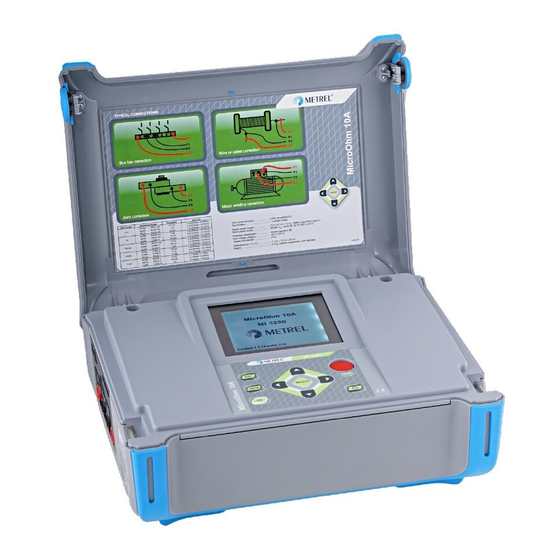
- Page 1 MicroOhm 10A MI 3250 Instruction manual Version 1.1.2, Code no 20 751 893...
- Page 2 Mark on your equipment certifies that this equipment meets the requirements of the EU (European Union) concerning safety and electromagnetic compatibility regulations © 2011 METREL No part of this publication may be reproduced or utilized in any form or by any means without permission in writing from METREL.
-
Page 3: Table Of Contents
MI 3250 MicroOhm 10A Table of contents Table of contents General description ..................... 5 Features ......................5 Safety and operational considerations .............. 6 Warnings and notes ..................6 Battery and charging ..................8 2.2.1 New battery cells or cells unused for a longer period ......9 Standards applied .................. - Page 4 MI 3250 MicroOhm 10A Table of contents Periodic calibration ..................35 Service ......................35 Technical specifications ................... 36 Resistance measurement ................36 Measurement parameters ................36 General data ....................37...
-
Page 5: General Description
MI 3250 MicroOhm 10A General description 1 General description 1.1 Features MicroOhm 10A (MI 3250) is a portable (2.8 kg) bidirectional low resistance ohmmeter using four wire Kelvin method to measure low resistances of: Switches Relays Connectors ... -
Page 6: Safety And Operational Considerations
2.1 Warnings and notes In order to maintain the highest level of operator safety while carrying out various tests and measurements Metrel recommends keeping your MicroOhm 10A instruments in good condition and undamaged. When using the instrument, consider the following general warnings: symbol on the instrument means »Read the Instruction manual with... - Page 7 MI 3250 MicroOhm 10A Safety and operational considerations Warnings related to measurement functions: Resistance and inductive measurement Resistance measurement should only be performed on de-energized objects! Do not touch the test object during the measurement or before it is fully ...
-
Page 8: Battery And Charging
If the instrument is not to be used for a long period of time, remove all batteries from the battery compartment. Alkaline or rechargeable Ni-Cd or Ni-MH batteries can be used. Metrel recommends only using rechargeable batteries with a capacity of 3500mAh or above. -
Page 9: New Battery Cells Or Cells Unused For A Longer Period
Cd cells can be subjected to these chemical effects (sometimes called the memory effect). As a result the instrument operation time can be significantly reduced during the initial charging/discharging cycles of the batteries. In this situation, Metrel recommend the following procedure to improve the battery lifetime: Procedure Notes Completely charge the battery. -
Page 10: Standards Applied
MI 3250 MicroOhm 10A Safety and operational considerations 2.3 Standards applied The MicroOhm 10A instrument is manufactured and tested in accordance with the following regulations: Electromagnetic compatibility (EMC) EN 61326 Electrical equipment for measurement, control and laboratory use – EMC requirements... -
Page 11: Instrument Description
MI 3250 MicroOhm 10A Safety and operational considerations 3 Instrument Description 3.1 Operator’s Panel The operator’s panel is shown in Figure 3.1 below. Figure 3.1: Front panel Legend: START / STOP Start or stop measurement. Switches the instrument power on or off. -
Page 12: Connectors And Battery Cover
MI 3250 MicroOhm 10A Instrument Description 3.2 Connectors and Battery cover The MicroOhm 10A tester contains the following terminals: Four banana safety sockets, for connection of test leads (Figure 3.2), Mains socket, for connection of mains supply cable (Figure 3.3), ... -
Page 13: Connector Panel (Right Side)
MI 3250 MicroOhm 10A Instrument description 3.2.2 Connector panel (right side) Figure 3.3: Communication and mains connectors Legend: Communication with PC RS232 port. 1 RS232 connector Communication with printer. 2 USB connector Communication with PC USB (1.1) port. 3 Mains connector... -
Page 14: Connector Panel (Left Side)
MI 3250 MicroOhm 10A Instrument description 3.2.3 Connector panel (left side) Figure 3.4: Measuring inputs/outputs and battery compartment Legend: Measuring inputs / outputs. Battery compartment. Figure 3.5: Correct inserted batteries Warnings! When connected to an installation, the instruments battery compartment ... -
Page 15: Accessories
The accessories consist of standard and optional accessories. Optional accessories can be delivered upon request. See attached list for standard configuration and options or contact your distributor or see the METREL home page: http://www.metrel.si. Figure 3.6: Standard set of the instrument Instrument MI 3250 MicroOhm 10A ... -
Page 16: Display Organization
MI 3250 MicroOhm 10A Instrument description 3.4 Display organization 1 Measurement result window 2 Measurement control window 3 Messages window 4 Battery and time indication Figure 3.7: Typical function display 3.4.1 Measurement result window Measurement window shows all relevant data during measurement campaign. -
Page 17: Measurement Control Window
MI 3250 MicroOhm 10A Instrument description 3.4.2 Measurement control window Control window permit user to modify control measurement parameters. Figure 3.9: Control window Mode allows user to select desired measuring mode. It is possible to select one of following modes: Single, Automatic, Continuous and Inductive. See chapter 5.2 for more details. -
Page 18: Battery And Time Indication
MI 3250 MicroOhm 10A Instrument Description Instrument is overheated. Measurement process is disabled. Battery supply voltage is low. P1, P2, C1 or C2 terminal is not connected to the instrument or too high resistance is detected. Measurement current and result is within defined limits. -
Page 19: Main Menu
MI 3250 MicroOhm 10A Main menu 4 Main menu 4.1 Instrument Main menu From the main menu of the instrument there are four options available: Measurement, Memory Menu, Settings Menu and Help Menu. Figure 4.1: Instrument Main menu Keys: Select one of the following menu items: <Measurement>... -
Page 20: Memory Menu
MI 3250 MicroOhm 10A Main menu 4.2 Memory Menu Measurement result with all relevant parameters can be stored into the instrument’s memory. The instrument’s memory space is divided into 2 levels: Object and Number of Results. The upper Object level can contain up to 199 locations. The number of measurements stored under single object location is not limited. -
Page 21: Recalling Results
MI 3250 MicroOhm 10A Main menu 4.2.2 Recalling results To enter Recall results menu in Memory menu SELECT key should be pressed. Figure 4.4: Recall Menu Figure 4.5: Recalled result screen Keys in Recall menu: Selects one of the following items [Object; No. of results]. -
Page 22: Deleting Results
MI 3250 MicroOhm 10A Main menu 4.2.3 Deleting results To enter Delete results menu in Memory menu SELECT key should be pressed. Single measurement or all measurements under selected Object can be deleted. Figure 4.6: Delete all measurements under selected Object Keys in Delete menu: ... -
Page 23: Settings Menu
MI 3250 MicroOhm 10A Main menu 4.3 Settings menu In the Settings menu different parameters and settings of the instrument can be viewed or set. Figure 4.7: Settings menu Keys: Select the setting to adjust or view: <Language> instrument language;... -
Page 24: Set Date And Time
MI 3250 MicroOhm 10A Main menu 4.3.3 Set Date and Time To enter Date and Time menu SELECT key should be pressed. Figure 4.8: Date and time menu Keys: Select the parameter to be changed. Decrees or increase the parameter. -
Page 25: Temperature Compensation
MI 3250 MicroOhm 10A Main menu 4.3.5 Temperature Compensation The temperature compensation is used to adjust the measured resistance, which depends on the ambient temperature, to the value it would have at the reference temperature. Figure 4.10: Compensation menu Figure 4.11: Coefficient menu Keys in Temperature Compensation menu: Select the parameter to be changed. - Page 26 MI 3250 MicroOhm 10A Main menu Example: temp 4100 temp temp temp 4100 ...
-
Page 27: Set Limits
MI 3250 MicroOhm 10A Main menu 4.3.6 Set Limits With Upper and Lower limits the user is allowed to set limit resistance values. Measured resistance is compared against those limits. Result is validated only if it is within the given limits. -
Page 28: Help Menu
MI 3250 MicroOhm 10A Main menu 4.4 Help Menu The Help menu contains schematic diagrams for illustrating how to properly connect the instrument to the various test objects. Keys in help menu: Selects next / previous help screen. -
Page 29: Measurement
MI 3250 MicroOhm 10A Measurement 5 Measurement 5.1 Four wire Kelvin method When measuring resistance <20 Ω it is advisable to use a four wire measurement technique (Figure 5.1), for achieving high accuracy. By using this type of measurement configuration the test lead resistance is not included in the measurement, and the need for lead calibrating and balancing is eliminated. -
Page 30: Resistance Measurement
MI 3250 MicroOhm 10A Measurement 5.2 Resistance measurement Test can be started from the Measurement screen. Before carrying out a test the parameters (Mode, Range and Current) can be edited. Figure 5.2: Resistance menu Test parameters for Resistance measurement Mode... -
Page 31: Single Mode
MI 3250 MicroOhm 10A Measurement Figure 5.4: Example of Resistance measurement result Note: Consider displayed warnings before starting measurement! 5.2.1 Single Mode Single mode makes a single bidirectional measurement. The instrument will measure resistance in both directions (thermal EMF elimination). The main result displayed on the ... -
Page 32: Automatic Mode
MI 3250 MicroOhm 10A Measurement The measurement is started and stopped by the user. Continuous measurement I/t plot Test Start Stop Figure 5.6: Continuous Mode Note: The Continuous Mode is especially helpful for troubleshooting. 5.2.3 Automatic Mode Automatic mode makes a single bidirectional measurement. The instrument will measure resistance in both directions (thermal EMF elimination) and started a single measurement every time the P1, P2, C1 and C2 are connected to the test object. -
Page 33: Inductive Mode
MI 3250 MicroOhm 10A Measurement Note about thermal EMF: A junction between two different metals produces a voltage related to a temperature difference (thermocouple). MicroOhm 10A eliminates the thermal EMF effect by measuring resistance in both directions I+ and I-. -
Page 34: Communication
MI 3250 MicroOhm 10A Communication 6 Communication The instrument can communicate with the HVLink PRO PC software. The following action is supported: Saved results can be downloaded and stored to a PC. A special communication program on the PC automatically identifies the instrument and enables data transfer between the instrument and the PC. -
Page 35: Maintenance
MI 3250 MicroOhm 10A Technical specification 7 Maintenance Unauthorized persons are not allowed to open the MicroOhm 10A instrument. There are no user replaceable components inside the instrument, except the battery. Warning: Disconnect all measuring accessory, mains supply and switch off the ... -
Page 36: Technical Specifications
MI 3250 MicroOhm 10A Technical specification 8 Technical specifications 8.1 Resistance measurement Test current Resistance Range Resolution Accuracy 0000,0 … 2000,0 µΩ 0,1 µΩ 00,000 … 20,000 mΩ 1 µΩ ±(0,25% Rdg + 0,01%FS) 10 A 000,00 … 200,00 mΩ... -
Page 37: General Data
MI 3250 MicroOhm 10A Technical specification 8.3 General data Battery power supply ......7.2 V DC (6 × 1.2 V NiMH), type HR14 (size C) Mains power supply ......90-260 V , 45-65 Hz, 50 W (300V CAT II) Battery charging time ......typical 5 h (3500 mAh) Battery operation time: Idle state ...........
Need help?
Do you have a question about the MI 3250 and is the answer not in the manual?
Questions and answers