Table of Contents
Advertisement
Advertisement
Table of Contents

Related Manuals for METREL MI 3321 MultiservicerXA


Summary of Contents for METREL MI 3321 MultiservicerXA
- Page 1 MultiservicerXA MI 3321 Instruction Manual Ver. 5.3.6, Code no. 20 751 513...
- Page 2 PE of installation part. Mark on your equipment certifies that it meets requirements of all subjected EU regulations No part of this publication may be reproduced or utilized in any form or by any means without permission in writing from METREL.
-
Page 3: Table Of Contents
MI 3321 MultiservicerXA Table of contents General description .................... 8 Warnings ......................9 Warning markings on connector panel ............10 Standards applied ................... 10 Instrument description ..................12 Front panel ...................... 12 Safety pre-tests ....................13 Symbols and messages .................. 14 Dual supply voltage operation ................. - Page 4 MI 3321 MultiservicerXA Table of contents 4.3.6 Reset instrument settings ................. 34 4.3.7 Communication settings ................35 4.3.8 Edit User / device data menu ..............36 4.3.8.1 Users submenu ..................... 36 4.3.8.2 Devices submenu ..................37 4.3.8.3 Test sites submenu ..................37 4.3.8.4...
- Page 5 MI 3321 MultiservicerXA Table of contents 6.3.11 Functional test ..................76 Autotest sequences ..................77 VDE organizer – general menu ............... 77 7.1.1 VDE organizer operation ................79 7.1.2 Example of creating a test sequence with VDE organizer ......80 Custom autotests ....................
- Page 6 MI 3321 MultiservicerXA Table of contents Setup menu ....................111 8.6.1 Instrument settings ................. 111 Machine testing operating mode ..............114 Single tests (machine testing) menu ............. 114 Measurements and inspections ..............115 9.2.1 Visual test ....................115 9.2.2 Continuity ....................116 9.2.2.1...
- Page 7 MI 3321 MultiservicerXA Table of contents 11.1.8 Touch leakage current ................165 11.1.9 Polarity test .................... 165 11.1.10 Clamp current test ................165 11.1.11 RCD test ..................... 165 10.2.12 PRCD test ................... 165 11.1.13 Functional test ..................165 11.1.14 HV test ....................165 11.1.15...
-
Page 8: General Description
Three communication ports (USB and 2 RS232C) for communication with PC, barcode reader/writer, printers and optional test adapters, Soft touch keyboard with cursor keys, Built in real time clock, Fully compatible with new METREL PATLink PRO PC software package. -
Page 9: Warnings
MI 3321 MultiservicerXA General description In PAT testing operating mode powerful functions for fast and efficient periodic testing are included: Pre-programmed test sequences, Fast testing with barcode identification systems, Test data can be uploaded from PC, On site comparisons between old and new test results can be performed, Enables on site printing of test labels. -
Page 10: Warning Markings On Connector Panel
MI 3321 MultiservicerXA General description 1.2 Warning markings on connector panel Refer to chapter 2.1 Front panel. 1.3 Standards applied The MultiservicerXA instrument is manufactured and tested according to the following regulations, listed below. Electromagnetic compatibility (EMC) Electrical equipment for measurement, control and laboratory use –... - Page 11 MI 3321 MultiservicerXA General description and without integral overcurrent protection for household and similar uses EN 50191 Erection and operation of electrical test equipment EN 61557-1 Electrical safety in low voltage distribution systems up to 1 000 V a.c. and 1 500 V d.c. - Equipment for testing, measuring or monitoring of...
-
Page 12: Instrument Description
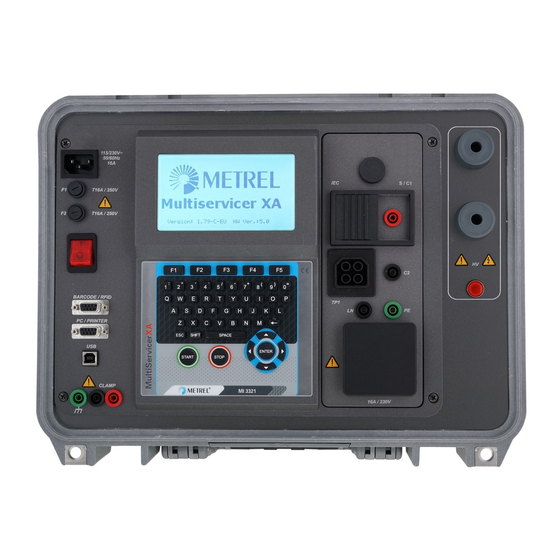
MI 3321 MultiservicerXA Instrument description Instrument description 2.1 Front panel Front panel Legend: 1 240 128 dots graphic matrix display with backlight. 2 Mains supply connector. 3 Two T16 A / 250 V fuses for instrument protection. 4 Mains switch with indicator. -
Page 13: Safety Pre-Tests
MI 3321 MultiservicerXA Instrument description intended for connection with shield of leakage current clamps only (e.g. A 1283). 9 Function keys intended for displayed defined options. 10 ESCAPE key. 11 START key. 12 STOP key. 13 Alpha-numeric keyboard. 14 Cursor keys and ENTER key. -
Page 14: Symbols And Messages
MI 3321 MultiservicerXA Instrument description Short circuit or too low resistance between L and N of tested device, Correct input mains voltage, Input PE connection. If pre-tests fail, an appropriate warning message will be displayed. The warnings and measures are described in chapter 2.3 Symbols and messages. - Page 15 MI 3321 MultiservicerXA Instrument description It is recommended to additionally check the DUT before proceeding with the test! Dangerous leakage current (higher than 3.5 mA) will flow if Leakage LN-PE high. power would be connected to DUT. Select YES or NO with Y or N key.
- Page 16 MI 3321 MultiservicerXA Instrument description Temperature of internal components of the instrument Overheated! reached their top limit. Measurement is prohibited until the internal temperature has reduced. Warning! More than 80 % of Instrument memory is almost full. Download stored results to memory is occupied.
-
Page 17: Dual Supply Voltage Operation
MI 3321 MultiservicerXA Instrument description The DUT should be switched on (to ensure that the complete circuit is tested). Connect the lead to be tested to the TP1 test terminal. Connect the cord to be tested to the IEC test terminal. -
Page 18: Technical Specifications
MI 3321 MultiservicerXA Technical specifications Technical specifications 3.1 Withstanding 1890 V, 2200 V Withstanding voltage Range Resolution Accuracy 0 V … 3000 V (3 % of reading + 5 digit) Withstanding current* Range Resolution Accuracy (10 % of reading + 8 digit) 0.0 mA …... -
Page 19: Discharging Time
MI 3321 MultiservicerXA Technical specifications 3.3 Discharging time Discharging time Range Resolution Accuracy (5 % of reading + 3 digit) 0.0 s … 9.9 s 0.1 s Peak voltage Range Resolution Accuracy 0 V… 550 V (5 % of reading + 5 digit) 2 wires system, triggered on DC voltage falling slope Max. -
Page 20: Insulation Resistance, Insulation - S Resistance
MI 3321 MultiservicerXA Technical specifications 3.5 Insulation resistance, Insulation – S resistance Insulation resistance Range Resolution Accuracy (10 % of reading + 5 digits) 0.000 M … 0.500 M 0.001 M 0.501 M … 1.999 M 0.001 M (5 % of reading + 3 digits) 2.00 M... -
Page 21: Differential Leakage Current
MI 3321 MultiservicerXA Technical specifications 3.7 Differential Leakage current Differential leakage current Range Resolution Accuracy (5 % of reading + 5 digits) 0.00 mA … 9.99 mA 0.01 mA Pass levels [mA]: ...... 0.25, 0.50, 0.75, 1.00, 1.50, 2.50, 3.00 mA, 3.50, 4.00, 4.50, 5.00, 5.50, 6.00, 7.00, 8.00, 9.00, none... -
Page 22: Clamp Current
MI 3321 MultiservicerXA Technical specifications 3.11 Clamp current True RMS current using 1000:1 current clamp Range Resolution Accuracy* (5 % of reading + 10 digits) 0.00 mA … 9.99 mA 0.01 mA (5 % of reading + 5 digits) 10.0 mA … 99.9 mA 0.1 mA... -
Page 23: Contact Voltage Rcd-Uc
MI 3321 MultiservicerXA Technical specifications -0.1I / +0; I = 0.5IN Test current shape: ....Sine-wave (AC), pulsed (A), smooth DC (B)* DC offset for pulsed current: ..6 mA (typical) RCD type: ......... G (non-delayed), S (time-delayed) Test current starting polarity: ..(+) or (-) Voltage range: ...... -
Page 24: Trip-Out Current
MI 3321 MultiservicerXA Technical specifications 0 ms … 500 ms 3 ms 1 ms Test current ........½I , 2I , 5I N N N N 300 mA (RCD types A, 5I is not available for I =1000 mA (RCD type AC) or I N... -
Page 25: Zs(Rcd), Rs(Rcd)
MI 3321 MultiservicerXA Technical specifications 10.0 … 99.9 loop resistance 100 … 999 measurement 1.00k … 9.99k 10.0k … 23.0k The accuracy is valid if mains voltage is stable during the measurement. Test current (at 230 V): ..... 6.5 A (10 ms) Nominal voltage range: ..... -
Page 26: Contact Voltage
MI 3321 MultiservicerXA Technical specifications Maximum test current (at 230 V):..154 A (10 ms) Calculation of prospective short-circuit current (standard voltage value): = 230 V 10 % L-PE Calculation of prospective short-circuit current (non-standard voltage value): × ×... -
Page 27: High Precision Line Impedance
MI 3321 MultiservicerXA Technical specifications Test current (at 230 V): ..... 6.5 A (10 ms) Nominal voltage range: ..... 30 V … 500 V (45 Hz … 65 Hz) Pass limits: ....... See Appendix C Test terminals: Z LINE TP1 test socket 3.15.1... -
Page 28: Voltage, Frequency, And Phase Rotation
MI 3321 MultiservicerXA Technical specifications 3.16 Voltage, frequency, and phase rotation 3.16.1 Phase rotation Result displayed 1.2.3 or 3.2.1 … 550 V Nominal system voltage range: 100 V Nominal frequency range: ..14 Hz … 500 Hz Test terminals: Phase rotation TP1 test socket 3.16.2... - Page 29 MI 3321 MultiservicerXA Technical specifications Power supply: ......Class I Pollution degree: ....... 2 Degree of protection: ....IP 50 (closed and locked cover) ..........IP 20 main test socket Case: ........shock proof plastic / portable Display: ........240*128 dots graphic matrix display with backlight Memory: ........
-
Page 30: Main Menu And Test Modes
MI 3321 MultiservicerXA Main menu and test modes Main menu and test modes The MultiservicerXA instrument has a user-friendly manipulation. By pressing only a few keys most of the actions can be done. The menu tree of the instrument has been designed to be simple to understand and easy to operate. -
Page 31: General Settings Menu
MI 3321 MultiservicerXA Main menu and test modes Instrument main menu Keys in instrument main menu: / Select one of the following menu items: <PAT TESTING>, a group of tests intended for testing electrical devices, see chapter 5;... -
Page 32: Setting Date And Time
MI 3321 MultiservicerXA Main menu and test modes <INSTRUMENT DATA>, various instrument settings; <CONTRAST>, LCD contrast; <ORIGINAL SETTINGS>, factory settings; <SET COMMUNICATION>, communication options; <EDIT DEVICE DATA>, data for tested equipment ; <PASSWORD>, to access restricted options; <RESULT>, to access menu for setting considered result. -
Page 33: Print Header
MI 3321 MultiservicerXA Main menu and test modes Language menu Keys in Language menu: / Select the language. ENTER Confirms selection and returns to General settings menu. Discards modifications and returns to General settings menu. 4.3.3 Print header Selecting this option will allow the user to enter text of printing header. -
Page 34: Display Contrast Adjustment
MI 3321 MultiservicerXA Main menu and test modes Firmware version. Instrument data menu Keys in instrument data menu: MORE (F1) Switches between multiple screens. 3Ph>Dat (F2) Receives instrument data from 3-Phase adapter. ENTER Returns to General settings menu. Note: ... -
Page 35: Communication Settings
MI 3321 MultiservicerXA Main menu and test modes Printer protocol is set to hardware handshaking – flow control (DTR). The following menu is displayed: Original settings menu Keys in instrument settings menu: Confirms reset to default values and returns to General settings menu. -
Page 36: Edit User / Device Data Menu
MI 3321 MultiservicerXA Main menu and test modes SAVE (F1) Confirms selection and returns to Set communications menu. Returns to Set communications menu without changes. Note: Only one port can be active at one time. 4.3.8 Edit User / device data menu Select User / device data in General settings menu with ... -
Page 37: Devices Submenu
MI 3321 MultiservicerXA Main menu and test modes SAVE (F1) Confirms entry and returns to User / device data menu. UNDO (F2) Discards modifications and returns to User / device data menu. 4.3.8.2 Devices submenu In this menu, default lists of device names (up to 100) can be edited. -
Page 38: Locations Submenu
MI 3321 MultiservicerXA Main menu and test modes Test sites submenu Keys in test sites menu: / PgUp (F2) Select the test site. PgDown (F3) ENTER Confirms selection and returns to User / device data menu. EDIT (F1) Confirms selection and opens Test site edit menu. -
Page 39: Password
MI 3321 MultiservicerXA Main menu and test modes Keys in user edit menu: Alphanumeric keys Entering location name. SAVE (F1) Confirms entry and returns to User / device data menu. UNDO (F2) Discards modifications and returns to User / device data menu. -
Page 40: Result
MI 3321 MultiservicerXA Main menu and test modes Password entry menu Keys in password entry menu: Alphanumeric keys Entering password. ENTER Accepts the password* and returns to Password menu. Discards modifications and returns to Password menu. Please take a note of this password and keep it in a safe place. - Page 41 MI 3321 MultiservicerXA Main menu and test modes Keys in Result settings menu: / Select Last or Worst option. SAVE (F1) Confirms selection and returns to General settings menu. UNDO (F2) Discards modifications and returns to General settings menu.
-
Page 42: Pat Testing Operating Mode
Note: For testing 3-phases appliances and/or welding machines the 3-phase operation mode must be enabled and the MultiservicerXA must be connected to a Metrel A1322 or A1422 3-phase Active GT / Machine adapter (Plus). 5.1 PAT testing main menu From the PAT testing main menu all instrument functions relevant for PAT testing can be selected. -
Page 43: Autotest Custom Menu
MI 3321 MultiservicerXA PAT testing operating mode See chapter 7.1 VDE organizer for more information. 5.3 Autotest custom menu The menu contains a list of custom prepared autosequences. Two sets (one for portable appliances and one for welding machines) of pre- programmed often used autotest sequences are added to the list by default. -
Page 44: Single Test Menu
MI 3321 MultiservicerXA PAT testing operating mode Autotest barcode/ tag menu Autotest barcode menu – portable appliances – welding machines See chapter 7.4 Barcode/TAG menu for more information. 5.6 Single test menu In single test menu individual tests can be performed. Two single test menus are available (one for portable appliances and one for welding machines). -
Page 45: Data Upload / Download Menu
MI 3321 MultiservicerXA PAT testing operating mode See chapters 8.2 Recalling results, 8.3 Deleting results and 8.4 Downloading and printing results for more information. 5.8 Data upload / download menu In this menu it is possible to upload different data from PC to the instrument:... - Page 46 MI 3321 MultiservicerXA PAT testing operating mode Instrument settings menu The following data can be controlled between tests: Device number, Test site, Location, User, Device name, Retest period Repairing code, Comments, Barcode systems. See chapter 8.6.1 Instruments settings for more information.
-
Page 47: Single Tests In Pat Testing Mode
Single test results cannot be saved in PAT testing operating mode. For testing 3-phase appliances or welding machines the 3-phase operation mode must be enabled and the MultiservicerXA must be connected to a Metrel 3-phase adapter: - A1322 – for 3-phase appliances, - A1422 –... -
Page 48: Measurements - Single Tests For Appliances
MI 3321 MultiservicerXA Single tests in PAT testing mode 6.2 Measurements – Single tests for appliances 6.2.1 Earth bond resistance This test ensures that the connections between the protective conductor terminal in the mains plug of the DUT and earthed accessible conductive parts of the DUT (metal housing) are satisfactory and of sufficiently low resistance. -
Page 49: Compensation Of Test Leads Resistance
MI 3321 MultiservicerXA Single tests in PAT testing mode Examples of earth bond resistance measurement results Displayed result: Main result ..... earth bond resistance Notes: Consider displayed warnings before starting measurement! HW 4.x or higher : When PRCD test is enabled in autotest sequence then mains supply voltage is applied on test socket during earth bond test (if selected in autotest sequence). - Page 50 MI 3321 MultiservicerXA Single tests in PAT testing mode This function is primarily intended for testing Class I DUTs. Insulation menu Test parameters for insulation resistance measurement OUTPUT Test voltage [250 V, 500 V] LIMIT Minimum resistance [0.10 M, 0.30 M, 0.50 M, 1.00 M, 2.00 M, 4.00 M, 7.00 M, 10.00 M, none]...
-
Page 51: Insulation Resistance - S
MI 3321 MultiservicerXA Single tests in PAT testing mode Connect device under test to the instrument (see figures above). For fixed equipment: Disconnect mains supply of the fixed equipment; Connect LN test socket of the instrument to L/N terminals of the fixed equipment;... - Page 52 MI 3321 MultiservicerXA Single tests in PAT testing mode Test parameters for insulation resistance measurement OUTPUT Test voltage [250 V, 500 V] LIMIT Minimum resistance [0.10 M, 0.25 M, 0.50 M, 1.00 M, 2.00 M, 4.00 M, 7.00 M, 10.00 M, none]...
-
Page 53: Substitute Leakage Current
MI 3321 MultiservicerXA Single tests in PAT testing mode Example of insulation S. resistance measurement results Displayed results: Main result ..... Insulation resistance (LN – S) Notes: If a Class I device is connected to the mains test socket the currents flowing through the PE terminal will not be considered. - Page 54 MI 3321 MultiservicerXA Single tests in PAT testing mode Test circuits for substitute leakage current measurement Measurement of substitute leakage current of class I DUT Measurement of substitute leakage current of fixed installed DUTs of class I Substitute leakage measurement procedure ...
-
Page 55: Substitute Leakage - S
MI 3321 MultiservicerXA Single tests in PAT testing mode Displayed results: Main result ..... substitute leakage current Notes: Consider any displayed warning before starting measurement! When S/C1 probe is connected during the test then the current through it is also considered. - Page 56 MI 3321 MultiservicerXA Single tests in PAT testing mode Measurement of substitute leakage current of class II DUT Measurement of substitute leakage of accessible isolated conductive parts of fixed installed DUTs Insulation resistance S measurement procedure Select the Substitute leakage S function.
-
Page 57: Differential Leakage Current
MI 3321 MultiservicerXA Single tests in PAT testing mode Notes: Consider any displayed warning before starting measurement! If a Class I device is connected to the mains test socket the currents flowing through the PE terminal will not be considered. -
Page 58: Touch Leakage Current
MI 3321 MultiservicerXA Single tests in PAT testing mode Differential current measurement procedure Select the Differential function. Set test parameters. Connect device under test to the instrument (see figure above). Press the START key for measurement. - Page 59 MI 3321 MultiservicerXA Single tests in PAT testing mode Test circuits for touch leakage current measurement Measurement of touch leakage current Measurement of touch leakage current on a fixed installed DUT Touch leakage current measurement procedure Select the Touch leakage function.
-
Page 60: Polarity Test
MI 3321 MultiservicerXA Single tests in PAT testing mode Notes: During the test, a mains voltage is connected to the DUT. If DUT contains moving parts, make sure that it is safely mounted or protected to prevent possible danger to the operator or damage to the DUT or surrounding environment! ... -
Page 61: Clamp Current Test
MI 3321 MultiservicerXA Single tests in PAT testing mode Polarity - Active test procedure Select the Polarity test function. Select the active test sub-function. Connect tested IEC cord with RCD protection to the 3 Phase adapter A1322 / A1422 (see A 1322 / A 1422 Instruction manual). - Page 62 MI 3321 MultiservicerXA Single tests in PAT testing mode Clamp current menu Test parameters for clamp current measurement LIMIT Maximum current [0.25 mA, 0.50 mA, 0.75 mA, 1.00 mA, 1.50 mA, 2.25 mA, 2.50 mA, 3.00 mA, 3.50 mA, 5.00 mA, 9.00 mA]...
-
Page 63: Prcd Test
METREL offers high quality current clamps for this application. Green socket is intended for current clamp shield terminal, if exists. This will improve measurement of leakage current. -
Page 64: Prcd Single Test
MI 3321 MultiservicerXA Single tests in PAT testing mode Circuits for testing PRCD Testing of portable RCD (PRCD) Testing of portable RCD (PRCD) using optional A 1447 adapter PRCD single test menu PRCD autotest menu 6.2.10.1 PRCD single test Trip-out time measurement procedure ... -
Page 65: Automatic Prcd Test
MI 3321 MultiservicerXA Single tests in PAT testing mode Connect test lead toTP1 test socket of the instrument and the PRCD’s output. Press the START key to perform measurement. If both current polarities are selected: Reactivate tested PRCD ... - Page 66 MI 3321 MultiservicerXA Single tests in PAT testing mode Step 1 Step 2 Step 3 Step 4 Step 5 and Step 6 Individual steps in PRCD autotest The test passes if the PRCD: Does not trip out at ½I tests, N...
-
Page 67: Power / Functional Test
MI 3321 MultiservicerXA Single tests in PAT testing mode 6.2.11 Power / Functional test The DUT’s power consumption is measured in this test. The apparent power is an useful indication of proper operation of the DUT. Power/functional test menu Test parameters for the Power / Functional test... -
Page 68: Measurements - Single Tests For Welding Machines
Note: For testing welding machines the 3-phase operation mode must be enabled and the MultiservicerXA must be connected to a METREL 3-phase adapter (A1422). 6.3.1 Continuity of the protective circuit This test ensures that the connections between the protective conductor terminal in the mains plug of the DUT and earthed accessible conductive parts of the DUT (metal housing) are satisfactory and of sufficiently low resistance. -
Page 69: Insulation Resistance (Supply Circuit To Protective Circuit)
MI 3321 MultiservicerXA Single tests in PAT testing mode Result screens: Examples of continuity measurement results Displayed results: Main result ..... resistance Note: Consider displayed warnings before starting measurement! For compensation of test leads Description in chapter 6.2.1.1 Compensation of test leads resistance can be used as reference. -
Page 70: Insulation Resistance (Welding Circuit To Protective Circuit)
MI 3321 MultiservicerXA Single tests in PAT testing mode Result screens: Examples of Insulation LN-PE measurement results Displayed results: Main result ..... Insulation resistance LN-PE Note: Consider displayed warnings before starting measurement! 6.3.3 Insulation resistance (welding circuit to protective circuit) The insulation resistance test checks the resistance between the welding circuit (outputs) and the protective circuit (protective earth) of the welding machine. -
Page 71: Insulation Resistance (Supply Circuit To Welding Circuit)
MI 3321 MultiservicerXA Single tests in PAT testing mode Result screens: Examples of Insulation W-PE measurement results Displayed results: Main result ..... Insulation resistance W-PE Note: Consider displayed warnings before starting measurement! 6.3.4 Insulation resistance (supply circuit to welding circuit) The insulation resistance test checks the resistance between primary supply circuit and the welding circuit (outputs) of the welding machine. -
Page 72: Insulation Resistance (Supply Circuit Of Class Ii Equipment To Accessible Surfaces)
MI 3321 MultiservicerXA Single tests in PAT testing mode Result screens: Examples of Insulation LN-W measurement results Displayed results: Main result ..... Insulation resistance LN-W Note: Consider displayed warnings before starting measurement! 6.3.5 Insulation resistance (supply circuit to accessible surfaces of... -
Page 73: Welding Circuit Leakage Current
MI 3321 MultiservicerXA Single tests in PAT testing mode Result screens: Examples of Insulation LN-P measurement results Displayed results: Main result ..... Insulation resistance LN-P Note: Consider displayed warnings before starting measurement! 6.3.6 Welding circuit leakage current The purpose of this test is to determine the sum of all leakage currents flowing from the welding outputs W1 or W2 to earth. -
Page 74: Primary Leakage Current
MI 3321 MultiservicerXA Single tests in PAT testing mode Examples of welding circuit leakage current measurement results Displayed results: Main result ..... welding circuit leakage current Notes: During the test, a mains voltage is connected to the welding machine. Consider safety precautions. -
Page 75: Touch Leakage Current
MI 3321 MultiservicerXA Single tests in PAT testing mode For more information refer to chapter Measurements according to IEC/ EN 60974-4, paragraph Primary leakage current in 3-phase adapter instruction manual. Examples of primary leakage current measurement results Displayed results: Main result ..... -
Page 76: Clamp Current Test
MI 3321 MultiservicerXA Single tests in PAT testing mode LIMIT DC Maximum voltage: 113 Vpeak, 141 Vpeak, None. Test circuit and measurement procedure for No load voltage measurement For more information refer to chapter Measurements according to IEC/ EN 60974-4, paragraph No load voltage in 3-phase adapter instruction manual. - Page 77 MI 3321 MultiservicerXA Autotest sequences Autotest sequences Autotest is the fastest and easiest way to test DUTs. During the autotest preprogrammed measurements runs automatically in a sequential way. The complete autotest results can be stored together with their associated DUT name and all related information.
- Page 78 MI 3321 MultiservicerXA Autotest sequences ACMP = accessible conductive part separated from earth With the VDE organizer any VDE 0701-0702 compatible test sequence can be created. The sequences cover virtually any maintenance or periodic test, regardless of DUT type, safety class, supply cord length, fuse type, etc.
- Page 79 MI 3321 MultiservicerXA Autotest sequences 7.1.1 VDE organizer operation Select VDE Organizer in PAT testing main menu. Example of VDE organizer screen Keys: / Select organizer item. / Set parameter in selected (highlighted) item. Returns to previous menu.
- Page 80 MI 3321 MultiservicerXA Autotest sequences 7.1.2 Example of creating a test sequence with VDE organizer A periodic test of an iron will be performed. Type: flatiron ABC Un 230V, 50Hz, 1000 VA The iron can be classified as followed: For a periodic testing a VDE 0701-0702 test is relevant.
- Page 81 For testing welding machines the 3 phase operation mode must be enabled and the MultiservicerXA must be connected to a METREL 3-phase adapter (A1422). See 3-phase adapter (A1322 / A1422) Instruction manual for more information. If more than 50 autotests are saved, »Out of memory« message is displayed.
- Page 82 MI 3321 MultiservicerXA Autotest sequences 7.2.1 Deleting an existing custom test sequence Delete selected custom autotest sequence Keys: Y/ N Confirms or rejects deleting of selected custom autotest sequence. Any other key Return back to custom autotest menu without changes.
- Page 83 MI 3321 MultiservicerXA Autotest sequences Save option Save as option Autotest custom Save menus Keys: / Select character in line. Alphanumeric Enters character. SHIFT+ Alphanumeric Enters small letter or special character. Deletes character left to cursor. SAVE (F1) Confirms saving custom autotest sequence under entered name.
- Page 84 MI 3321 MultiservicerXA Autotest sequences 7.3 Project autotests The Project autotests is an unique tool that dramatically simplifies and speeds up repeated (periodic) testing of DUTs. The main idea is to re-use known stored data (either in instrument or on a PC) of the tested DUT.
- Page 85 MI 3321 MultiservicerXA Autotest sequences When searching for stored autotest results the following filters can be used to narrow the hits: Device number, User, Test site, Location, Date from and date to. Keys: / Select filter line. / , Alphanumeric Edits selected filter.
- Page 86 MI 3321 MultiservicerXA Autotest sequences Keys: / PgUp (F1) Select the DUT that should be retested. PgDown (F2) ENTER Recalls autotest project results for selected DUT. START Starts running new autotest for selected DUT, see 7.3.2 Starting a project autotest Returns to Main menu.
- Page 87 MI 3321 MultiservicerXA Autotest sequences 7.3.2 Starting a project autotest Select Project Autotest in PAT testing main menu. Using the filters, search for the DUTs to be retested. After the DUT is found and selected (in Project autotest result menu) begin retesting the DUT by pressing the START key.
- Page 88 MI 3321 MultiservicerXA Autotest sequences New earth bond result is lower than old one. Difference between old and new result of particular test is so small that can be treated as the same. Example: New insulation resistance result stays at the same level as old result.
- Page 89 MI 3321 MultiservicerXA Autotest sequences 7.4.1 Working with RFID tags To use RFID system, connect RFID reader/writer to DB-9 female BARCODE connector first. See RFID reader/writer Instruction manual for more information. Connecting RFID tag reader/writer to the instrument MultiservicerXA Note: ...
- Page 90 MI 3321 MultiservicerXA Autotest sequences Keys: / Select the option. ENTER Opens menu for selected option. Returns to Barcode/tag menu. If no test results were stored in RFID tag, the View results option won’t be displayed. The following actions can be performed now:...
- Page 91 MI 3321 MultiservicerXA Autotest sequences Connecting barcode reader to the MultiservicerXA instrument Reading autotest sequence using barcode Select Barcode test in Barcode/tag menu and press ENTER key. The latest received or set autotest sequence name and its code is displayed A new autotest sequence received from the barcode reader will be accepted by the instrument (refer to Appendix A for available autotest sequences and its codes).
- Page 92 MI 3321 MultiservicerXA Autotest sequences 7.5 Performing autotest sequences – for appliances 7.5.1 Visual inspection A thorough visual check must be carried out before each electrical safety test. Following items should be checked: Inspection of DUT for sign of damage.
- Page 93 MI 3321 MultiservicerXA Autotest sequences HELP (F2) Displays the earth bond test help screens. REPEAT (F3) Repeats the earth bond resistance measurement. ENTER Proceeds to the next autotest sequence measurement (in continuous measurement mode only). SKIP (F4) Skips earth bond resistance measurement.
- Page 94 MI 3321 MultiservicerXA Autotest sequences (in continuous mode). Proceeds to the next autotest sequence measurement (in single measurement mode only). HELP (F2) Displays the insulation resistance S measurement help screens. REPEAT (F3) Repeats the insulation resistance S measurement. ENTER Proceeds to the next autotest sequence measurement (in continuous measurement mode only).
- Page 95 MI 3321 MultiservicerXA Autotest sequences 7.5.7 Differential leakage current Measurement is described in chapter 6.2.6 Differential leakage current. If the differential leakage test fails or was skipped other tests will not be carried out because of safety. Keys START Starts the leakage current measurement.
- Page 96 MI 3321 MultiservicerXA Autotest sequences REPEAT (F3) Repeats the polarity test. SKIP (F4) Skips polarity test. END (F5) Ends the autotest sequence. 7.5.10 TRMS current measurement using clamp current adapter Measurement is described in chapter 6.2.9 Clamp current measurement. If the current clamp test fails or was skipped other tests will not be carried out because of safety.
- Page 97 MI 3321 MultiservicerXA Autotest sequences Safety relevant functions (alarms, switches etc) A PASS/ FAIL ticker can be committed manually. The power measurement can be carried out optionally and is stored too. The Power measurement is described in chapter 6.2.11 Power / Functional test.
- Page 98 MI 3321 MultiservicerXA Autotest sequences Visual test menu Keys: PASS (F1) Confirms that the visual inspection passed. SKIP (F4) Skips visual test. FAIL (F5) Ends the autotest sequence. 7.6.2 Continuity of the protective circuit Measurement is described in chapter 6.3.1 Continuity of the protective circuit.
- Page 99 MI 3321 MultiservicerXA Autotest sequences measurement mode only). ENTER Proceeds to the next autotest sequence measurement (in continuous measurement mode only). HELP (F2) Displays the insulation resistance test help screens. REPEAT (F3) Repeats the insulation resistance measurement. SKIP (F4) Skips insulation resistance measurement.
- Page 100 MI 3321 MultiservicerXA Autotest sequences 7.6.6 Insulation resistance (supply circuit of class II equipment to accessible surfaces) Measurement is described in chapter 6.3.5 Insulation resistance (supply circuit of class II equipment to accessible surfaces). If this insulation test fails or was skipped other tests will not be carried out because of safety.
- Page 101 MI 3321 MultiservicerXA Autotest sequences START Starts the leakage current measurement. Proceeds with the next leakage current measurement (in continuous mode). Proceeds to the next autotest sequence measurement (in single measurement mode only). ENTER Proceeds to the next autotest sequence measurement (in continuous measurement mode only).
- Page 102 MI 3321 MultiservicerXA Autotest sequences REPEAT (F3) Repeats the no voltage measurement. SKIP (F4) Skips leakage current measurement. END (F5) Ends the autotest sequence. 7.6.11 TRMS current measurement using clamp current adapter Refer to chapter 6.2.9 TRMS current measurement using clamp current adapter for reference.
- Page 103 MI 3321 MultiservicerXA Working with autotest results Working with autotest results After the autotest sequence is completed, measurement results can be: Saved to the flash memory of the instrument. Before that they can be viewed and edited. Refer to chapter 8.1 Saving autotest results for more information.
- Page 104 MI 3321 MultiservicerXA Working with autotest results In the Comments field, up to 25 alpha-numeric or special characters can be entered. All parameters added to the autotest results have, in general, a possibility to be replicated or default set to blank when saving new autotest results. Device number can also be automatically incremented when new autotest sequence is finished.
- Page 105 MI 3321 MultiservicerXA Working with autotest results Keys: / Selects parameter line. / , Alphanumeric Edits parameter line. FIND (F1) Starts search after filters are set correctly. UNDO (F2) Undo latest change. TYPE (F3) Selects parameter line type.
- Page 106 MI 3321 MultiservicerXA Working with autotest results View results menu Use the ESC key to return to Recall memory or Search results menus. From the Recall memory menu stored data can be downloaded to a PC, printed out to a serial printer or deleted from the memory. Refer to chapters 8.4 Downloading and printing results and 8.3 Deleting results, respectively.
- Page 107 MI 3321 MultiservicerXA Working with autotest results 8.4 Downloading and printing results The instrument offers the following possibilities to send selected result or selection to: PC (to store and later operations on stored results), Serial printer for fast report printing, Label printer, and RFID tag (only one result).
- Page 108 MI 3321 MultiservicerXA Working with autotest results Send to serial printer Send to serial printer menu Keys: SET (F2) Opens menu for selection of data transfer control option. Serial printer settings Keys: / Selects the option. SAVE (F1) Accepts selected option.
- Page 109 MI 3321 MultiservicerXA Working with autotest results ......METREL Testing laboratory Horjul, Slovenia ......DEVICE 11072010 TEST SITE METREL LOCATION OFFICE 1 TIME/DATE 09:31 11-JUL-2008 USER TOMAZ RESULT: PASS ---------------------------------------- VISUAL PASS EARTH BOND It: 10A~ Rlim: 0.10 Ohm 1. R = 0.03 Ohm PASS INSULATION Ut: 500V Rlim: 1.00 MOhm...
- Page 110 MI 3321 MultiservicerXA Working with autotest results Select label printer menu Keys: / Selects the printer. SAVE (F1) Accepts selected printer. ENTER Returns to Send results menu. Refer to chapter 8.6.1 Instrument settings and Appendix B for detailed information about barcode systems used when printing barcode labels.
- Page 111 MI 3321 MultiservicerXA Working with autotest results Keys: ENTER Sends data to the RFID tag. Returns to Send results menu. 8.5 Data upload / download Autotests and results from PC software can be uploaded to the instrument from the Data upload / download menu. Also the following items can be downloaded and...
- Page 112 MI 3321 MultiservicerXA Working with autotest results DUT name, retest period repairing code, comments, barcode system, save and print. From the Main menu, select Setup and then select Instrument settings by using and cursor keys and press ENTER key to confirm. The Instrument settings submenu will be displayed.
- Page 113 MI 3321 MultiservicerXA Working with autotest results The increment option can also be set in the device number field. In this case, the DUT number will be automatically incremented when new autotest sequence is finished. Special character »$« between autotest shortcut code and DUT name (ID number) ...
- Page 114 MI 3321 MultiservicerXA Machine testing operating mode Machine testing operating mode The Machine testing operating mode is primarily intended for testing of electrical safety of machines according to the standard IEC/ EN 60204. After entering the Machine testing menu following options are displayed: Single test menu (see 9.1),...
- Page 115 MI 3321 MultiservicerXA Machine testing operating mode <Functional test> Functional inspection. ENTER Enters selected test. Returns to Main menu. Note: Unlike in PAT testing mode all single test results and parameters can be stored for documentation purposes (view chapter 12.1 for more information).
- Page 116 MI 3321 MultiservicerXA Machine testing operating mode Visual test procedure Select the VISUAL TEST function. Perform visual inspection of the machine. Commit PASS or FAIL ticker manually (with PASS (F1), FAIL (F5) keys. Save result (optionally) with SAVE (F4) key.
- Page 117 MI 3321 MultiservicerXA Machine testing operating mode Test circuit for Continuity measurement Measurement of continuity of protective conductors of machines 9.2.2.1 Single continuity test In the single continuity test the continuity of individual connections can be determined. Continuity measurement procedure ...
- Page 118 MI 3321 MultiservicerXA Machine testing operating mode Examples of continuity measurement results Displayed results: Main result ..... Continuity Notes: Consider displayed warnings before starting measurement! For more information how to calibrate the test leads see chapter 9.2.2.3. 9.2.2.2...
- Page 119 MI 3321 MultiservicerXA Machine testing operating mode Disconnect test leads and proceed to the next measuring point. (no beep) ...... Connect test leads to both ends of the last PE connection under test. The instrument detects (double beep) the low resistance and starts last measurement.
- Page 120 MI 3321 MultiservicerXA Machine testing operating mode 9.2.2.3 Compensation of test leads resistance Test leads compensation is required to eliminate the influence of test leads resistance and instrument's internal resistance. If a compensation value is stored this is indicated in the message C.
- Page 121 MI 3321 MultiservicerXA Machine testing operating mode Test parameters for insulation resistance measurement OUTPUT Test voltage [250 V, 500 V] LIMIT Minimum resistance [0.10 M, 0.30 M, 0.50 M, 1.00 M, 2.00 (Insulation) M, 4.00M, 7.00 M, 10.00 M, none]...
- Page 122 MI 3321 MultiservicerXA Machine testing operating mode Examples of insulation resistance measurement results Displayed results: Main result ..... insulation resistance Notes: The machine under test should be de-energized before the measurement! Consider any warning on the display before starting the measurement! ...
- Page 123 MI 3321 MultiservicerXA Machine testing operating mode Do not perform this test if any damage or abnormality (test leads, instrument) is noted! Never touch exposed probe tip, connections equipment under test or any other energized part during the measurements.
- Page 124 MI 3321 MultiservicerXA Machine testing operating mode High voltage withstanding test High voltage withstanding test procedure Select the HV-test single test. Enter correct Password HV-test (as set in General settings >> Password menu). Set test parameters ...
- Page 125 MI 3321 MultiservicerXA Machine testing operating mode *Notes: Before first use and after “Original Settings”, Password HV-test must be set in General settings >> Password menu. If a 5 s start timer runs out, HV-test will not start for safety. Initiate start measurement procedure with STOP key and start test within a 5 s delay.
- Page 126 MI 3321 MultiservicerXA Machine testing operating mode Loop impedance menu Test parameters for fault loop impedance measurement TEST Type of test based on installed protective device: [Zloop, Zs(rcd)*, Rs(rcd)*, Z mL-Pe*** ] Fuse type Selection of Fuse type [*F, NV, gG, B, C, K, D] ** For Z LOOP, Zs(rcd), Z mL-Pe...
- Page 127 MI 3321 MultiservicerXA Machine testing operating mode Measurement of fault loop impedance Fault loop impedance measurement procedure Select the Z LOOP single test. Set test parameters. Connect the three wire test lead to the TP1 port on the instrument.
- Page 128 MI 3321 MultiservicerXA Machine testing operating mode Examples of fault loop impedance measurement results Displayed results: Main result ..... Fault loop impedance, ......Prospective fault current, Ul-pe ...... Voltage UL-PE Un-pe ..... Voltage UN-PE Input voltage (L-PE) (93 V U ...
- Page 129 MI 3321 MultiservicerXA Machine testing operating mode *F Means no fuse selected. Additional key: Toggles between result screens. Test setup for Z mL-Pe fault loop impedance measurement Connection of impedance adapter to the instrument Z mL-Pe fault loop impedance measuring procedure Connect Impedance adapter to the instrument (see figure above).
- Page 130 MI 3321 MultiservicerXA Machine testing operating mode Example of Z m L-Pe loop measurement results Displayed results: Z ......Loop impedance, ...... Prospective fault current, R......Resistive part of line impedance, Xl ....... Reactive part of line impedance. The following parameters are displayed in sub-screen for loop impedance measurement: IscMaxL-Pe ..
- Page 131 MI 3321 MultiservicerXA Machine testing operating mode RCD test menu Test parameters for RCD test and measurement TEST RCD sub-function test [Tripout time - RCDt, Uc, AUTO, Tripout current]. Rated RCD residual current sensitivity I [10 mA, 30 mA, 100 mA, 300 N...
- Page 132 MI 3321 MultiservicerXA Machine testing operating mode Test circuit for RCD tests RCD tests (machine testing) 9.2.6.1 Contact voltage (RCD Uc) The contact voltage test verifies that RCDs and earthing arrangement are effective. The contact voltage is measured with a test current lower than ½ I to avoid trip-out of the N...
- Page 133 MI 3321 MultiservicerXA Machine testing operating mode The displayed contact voltage is proportional to the rated nominal residual current of the RCD and multiplied by appropriate factor. The 1.05 factor is applied to avoid negative tolerance of result. An additional factor depends on RCD type and type of test current.
- Page 134 MI 3321 MultiservicerXA Machine testing operating mode 9.2.6.2 Trip out time (RCD t) Trip-out time measurement verifies the sensitivity of an RCD, at different test currents. Trip out time measurement procedure Select the RCD t single test. Set test parameters.
- Page 135 MI 3321 MultiservicerXA Machine testing operating mode Trip out current measurement procedure Select the RCD I single test. Set test parameters. Connect three wire test lead to the TP1 test port on the instrument. Connect the three wire test lead to L,N (downstream of the RCD) and PE terminals of the machine.
- Page 136 MI 3321 MultiservicerXA Machine testing operating mode RCD should trip-out Test with IN, (-) (step 2). Re-activate RCD. RCD should trip-out Test with 5IN, (+) (step 3). Re-activate RCD. RCD should trip-out Test with 5IN, (-) (step 4).
- Page 137 MI 3321 MultiservicerXA Machine testing operating mode Notes: The autotest sequence is immediately stopped if any incorrect condition is detected, e.g. excessive Uc or trip-out time out of limits. The RCD t test will trip the RCD. Assure that the instrument is not powered from a socket protected by the tested RCD.
- Page 138 MI 3321 MultiservicerXA Machine testing operating mode expected Line voltage Measured voltage Discharging time menu Test parameters for Discharging Time Limit U Rated maximal residual voltage. [60 V]. Limit t Rated maximal discharging time [1 s, 5 s].
- Page 139 MI 3321 MultiservicerXA Machine testing operating mode Test circuit for Discharging Time test Discharging time test Discharging time measurement procedure Select the Discharging Time single test. Set test parameters. Connect three wire test cable to the TP1 test port on the instrument.
- Page 140 MI 3321 MultiservicerXA Machine testing operating mode Interpretation of the “Repeat” message It is not possible to differentiate between a disconnection moment at very low voltage and a machine with a very low discharging time. In both cases the reading will be 0.0 s together with the “Repeat”...
- Page 141 MI 3321 MultiservicerXA Machine testing operating mode Voltage menu Test parameters for Voltage single test There are no parameters to be set in this function.
- Page 142 MI 3321 MultiservicerXA Machine testing operating mode Test circuit for Voltage test Voltage test Voltage and rotary filed measurement procedure Select the Voltage single test. The measurement starts immediately after entering in the Voltage menu. Connect three wire test cable to the TP1 test port on the instrument.
- Page 143 MI 3321 MultiservicerXA Machine testing operating mode Examples of voltage measurement results Displayed results for single phase system: Ul-n ......Voltage between phase and neutral conductors, Ul-pe ...... Voltage between phase and protective conductors, Un-pe ..... Voltage between neutral and protective conductors, f......
- Page 144 MI 3321 MultiservicerXA Machine testing operating mode Functional test menu Functional test procedure Select the Functional test function. Perform visual inspection of the machine functionality. Commit PASS (F1) or FAIL (F5) ticker manually. Save result with SAVE (F4) key (optional).
- Page 145 MI 3321 MultiservicerXA Switchgear testing operating mode 10 Switchgear testing operating mode The Switchgear testing operating mode is primarily intended for testing of electrical safety of switchgear according to the standard IEC/ EN 60439. After entering the Switchgear testing menu following options are displayed: Single test menu (see 10.1),...
- Page 146 MI 3321 MultiservicerXA Switchgear testing operating mode <RCD test>, Tests of residual current devices. <PRCD test> Tests of portable residual current devices, <Functional test>, Functional inspection. <Power>, Power consumption test. ENTER Enters selected test. Returns to Main menu. Note: ...
- Page 147 MI 3321 MultiservicerXA Switchgear testing operating mode Commit PASS or FAIL ticker manually (with PASS(F1), FAIL(F5) keys. Save result (optionally) with SAVE key Examples of visual test measurement results 10.2.2 Continuity This test determines that the PE and equipotential connections inside the switchboard have a proper resistance that corresponds to their length and cross-section.
- Page 148 MI 3321 MultiservicerXA Switchgear testing operating mode Measurement of continuity of protective conductors of switchboards 10.2.2.1 Single continuity test In the single continuity test the continuity of individual connections can be determined. Continuity measurement procedure Select the CONTINUITY function.
- Page 149 MI 3321 MultiservicerXA Switchgear testing operating mode Examples of continuity measurement results Displayed results: Main result ..... Continuity Notes: Consider displayed warnings before starting measurement! For more information how to calibrate the test leads see chapter 10.2.2.3 Compensation of test leads resistance.
- Page 150 MI 3321 MultiservicerXA Switchgear testing operating mode sound signal (continuous short beeps) indicates that the second measurement is concluded and temporarily stored. The results displayed in this phase will not be stored. Disconnect test leads and proceed to the next measuring point. (no beep) ...
- Page 151 MI 3321 MultiservicerXA Switchgear testing operating mode 10.2.2.3 Compensation of test leads resistance Test leads compensation is required to eliminate the influence of test leads resistance and instrument's internal resistance. If a compensation value is stored this is indicated in the message. Refer to chapter 9.2.2.3 Compensation of test resistance for more information.
- Page 152 MI 3321 MultiservicerXA Switchgear testing operating mode Test circuits for insulation resistance measurement Measurement of insulation resistance Insulation resistance measurement Select the Insulation single test. Set test parameters. Connect test leads to LN and PE terminals on the instrument.
- Page 153 MI 3321 MultiservicerXA Switchgear testing operating mode Examples of insulation resistance measurement results Notes: The switchboard under test should be de-energized before the measurement! Consider any warning on the display before starting the measurement! Care must be taken if switchboard includes sensitive electrical equipment that could be damaged if to high test voltage would be applied to them.
- Page 154 MI 3321 MultiservicerXA Switchgear testing operating mode Connect test probes only for the High Voltage test and disconnect them immediately after the test! DO NOT touch any part of test probe in front of the barrier (keep your fingers behind the finger guards on the probe) –...
- Page 155 MI 3321 MultiservicerXA Switchgear testing operating mode Test circuit for high voltage withstanding test High voltage withstanding test High voltage withstanding test Select the HV-test single test. Enter correct Password HV-test (as set in General settings >> Password menu).
- Page 156 MI 3321 MultiservicerXA Switchgear testing operating mode *Notes: Before first use and after “Original Settings”, Password HV-test must be set in General settings >> Password menu. If a 5 s start timer runs out, HV-test will not start for safety. Initiate start measurement procedure with STOP key and start test within a 5 s delay.
- Page 157 MI 3321 MultiservicerXA Switchgear testing operating mode EQUIPMENT UNDER disconnect TEST MultiServicer TP1-L 3321 rest voltage TEST test TP1-N Test circuitry expected Line voltage Measured voltage Discharging time menu Test parameters for Discharging Time Limit U Rated maximal residual voltage [120 V].
- Page 158 MI 3321 MultiservicerXA Switchgear testing operating mode Test circuit for Discharging Time test Discharging time test Trip out current measurement procedure Select the Discharging Time single test. Set test parameters. Connect three wire test cable to the TP1 test port on the instrument.
- Page 159 MI 3321 MultiservicerXA Switchgear testing operating mode Interpretation of the “Repeat” message It is not possible to differentiate between a disconnection moment at very low voltage and a switchboard with a very low discharging time. In both cases the reading will be 0.0 s together with the “Repeat”...
- Page 160 MI 3321 MultiservicerXA Switchgear testing operating mode Voltage menu Test parameters for Voltage single test There are no parameters to be set in this function. Test circuit for Voltage test Voltage test...
- Page 161 MI 3321 MultiservicerXA Switchgear testing operating mode Voltage and rotary filed measurement procedure Select the Voltage single test. The measurement starts immediately after entering in the Voltage menu. Connect three wire test cable to the TP1 test port on the instrument.
- Page 162 MI 3321 MultiservicerXA Switchgear testing operating mode Scope of test Check following items while the switchboard is operating: Temperature regulators, monitors, RCDs and other disconnection devices, Operation of functional disconnection devices, Operation of switches, lamps, keys Rotating parts, motors, pumps Power consumption Etc.
- Page 163 MI 3321 MultiservicerXA All tests operating mode 11 All tests operating mode The All tests operating mode is primarily intended for testing of electrical safety of all kinds of electrical equipment. All measurements available in the instrument can be started from this operating mode.
- Page 164 MI 3321 MultiservicerXA All tests operating mode <Sub Leakage-S>, Substitute leakage current, Class II parts. <Leakage>, Differential leakage current. <Touch Leakage>, Touch leakage current. <Polarity test>, Polarity of IEC cords. <Clamp current>, Load and leakage currents with current clamp. <RCD test>, Tests of portable and standard residual current devices.
- Page 165 MI 3321 MultiservicerXA All tests operating mode 11.1.6 Substitute leakage current - S Description in chapter 6.2.5 Substitute leakage-S can be used as reference. 11.1.7 Leakage current Description in chapter 6.2.6 Differential leakage current can be used as reference. 11.1.8 Touch leakage current Description in chapter 6.2.7 Touch Leakage can be used as reference.
- Page 166 MI 3321 MultiservicerXA All tests operating mode values set on base of selected protective circuit breakers. The measurement complies with requirements of the standard EN 61557-3. Warning! MI 3321 checks voltages on TP1 before running test and disables test in case hazardous live voltage is detected on TP1 PE.
- Page 167 MI 3321 MultiservicerXA All tests operating mode Test circuit for line impedance measurement Measurement of line impedance Line impedance measurement procedure Select the Z LINE single test. Select type of test. Set test parameters. Connect the three wire test lead to the TP1 port on the instrument.
- Page 168 MI 3321 MultiservicerXA All tests operating mode Examples of line impedance measurement results Displayed results: Main result ..... Line impedance, ......Prospective fault current, Ul-n ......Voltage UL-N Prospective short circuit current I is calculated from measured impedance as follows: ...
- Page 169 MI 3321 MultiservicerXA All tests operating mode Test parameters for low line impedance measurement Function Z-LINE Test Impedance function [Z m L-N, Z m L-L] FUSE type Selection of fuse type [*F, NV, gG, B, C, K, D] FUSE I Rated current of selected fuse.
- Page 170 MI 3321 MultiservicerXA All tests operating mode Low line impedance measuring procedure Connect Impedance adapter to the instrument (see figure above). Select the Z-LINE function. Enable and set fuse type (optional). Power ON the Impedance adapter (ON/OFF key, green LED lits).
- Page 171 MI 3321 MultiservicerXA All tests operating mode IscStd ..... Standard prospective short-circuit current. Notes: For application and technical data of the Impedance adapter A1143 see its Instruction manual 20 750 859. High fluctuations of mains voltage can influence the measurement results.
- Page 172 Working with results – all operating modes MI 3321 MultiservicerXA 12 Working with results in Machine testing, Switchgear testing and All tests operating mode 12.1 Memory organization The Machine, Switchgear and All tests operating mode are sharing the same memory structure.
- Page 173 Working with results – all operating modes MI 3321 MultiservicerXA Keys: / Selects the item. / , alphanumeric Edits data. SAVE (F1) Saves test results and returns to last single test menu. UNDO (F2) Undoes changes. LIST (F5) Enters list of pre-defined names.
- Page 174 Working with results – all operating modes MI 3321 MultiservicerXA / , Alphanumeric Edits parameter line. FIND (F1) Starts search after filters are setup correctly. UNDO (F2) Undoes latest change. TYPE (F3) Selects type of parameter line. Returns to Main menu.
- Page 175 Working with results – all operating modes MI 3321 MultiservicerXA View Project results menus Some single tests contain more parameters and results that can not be seen in one display line. In this case »>>« is in the result column. For view the results select the single test with ...
- Page 176 Working with results – all operating modes MI 3321 MultiservicerXA 12.5 Deleting project(s) All data in a stored project can also be deleted from the memory. Recall the result(s) you want to delete (Refer to chapter 12.2 Recalling projects for detailed information on recalling results).
- Page 177 Working with results – all operating modes MI 3321 MultiservicerXA Send results menu Keys: / Selects activity. ENTER Starts sending to selected output. (F1), (F2) Modification of communication parameters. Returns to memory recall menu. Parameters for SEND TO: PC...
- Page 178 Working with results – all operating modes MI 3321 MultiservicerXA Serial printer settings Keys / Selects the option. SAVE (F1) Accepts selected option. Returns to Send results menu....... METREL Testing laboratory Horjul, Slovenia ......DEVICE 11072010 TEST SITE METREL...
- Page 179 MI 3321 MultiservicerXA Maintenance 13 Maintenance 13.1 Periodic calibration It is essential that all measuring instruments are regularly calibrated in order for the technical specification listed in this manual to be guaranteed. We recommend an annual calibration. The calibration should be done by an authorized technical person only.
- Page 180 MI 3321 MultiservicerXA Instrument set and accessories 14 Instrument set and accessories Standard set of the instrument Instrument MI 3321 Multiservicer XA Bag for accessories Mains cable (2 m, wire cross-section 3 x 1.5 mm HV test probes (2 m), 2 pcs ...
- Page 181 Appendix A – Preprogrammed autotests MI 3321 MultiservicerXA Appendix A – Preprogramed autotests Pre-programmed autotest sequences Name Description Testing according to VDE 0701-0702. Class 1 device. 1 Cl_1_Iso Insulation resistance and substitute leakage current measurements are selected. Testing according to VDE 0701-0702.
- Page 182 Appendix A – Preprogrammed autotests MI 3321 MultiservicerXA Pre-programmed autotest sequences table Autotest shortcut code Cl_1_Iso Cl1_Iso_BLT Cl_1_Ia Cl_1_Ia_BLT Visual test Output 200 mA 200 mA 200 mA 200 mA 0.30 0.30 0.30 ...
- Page 183 Appendix A – Preprogrammed autotests MI 3321 MultiservicerXA Pre-programmed autotest sequences table (cont’d) Autotest shortcut code Cl_2_Iso Cl_2_Ibs Cl_1_IsoIa Cl1_IsoIaBLT Visual test Output 200 mA 200 mA 0.30 0.30 Earth bond Limit ...
- Page 184 Appendix A – Preprogrammed autotests MI 3321 MultiservicerXA Pre-programmed autotest sequences table (cont’d) Autotest shortcut code Cl_2_IsoIbs Cl_2 Cl_3_Iso Cl_3 Visual test Output Earth bond Limit ...
- Page 185 Appendix A – Preprogrammed autotests MI 3321 MultiservicerXA METREL GmbH VDE tester test type card Code Autotest sequence name and descriptions Limits Barcode Testing according to VDE. Earth bond: 0.30 Class 1 device. Kl_1_Iso Insulation resistance and substitute Insulation: 1.00 M...
- Page 186 Appendix A – Preprogrammed autotests MI 3321 MultiservicerXA METREL GmbH VDE tester test type card (cont'd) Testing according to VDE. Kl_2 Class 2 device without any isolated accessible conductive parts. A1 0 Testing according to VDE. Insulation - S: 0.25 M...
- Page 187 Appendix A – Preprogrammed autotests MI 3321 MultiservicerXA Pre-programmed autotest sequences table – welding machines Autotest shortcut code - Welding machines Kl1_≤32A_Risiko Kl1_≤32A_Normal Kl1_Iso_RisUmg Kl1_ Iso_NorUmg Kl1_Iso_Schutz Visual test Output 200 mA 200 mA 200 mA...
- Page 188 Appendix A – Preprogrammed autotests MI 3321 MultiservicerXA Pre-programmed autotest sequences table – welding machines (cont’d) Autotest shortcut code Welding machines Kl1_≤32A_Schutz Kl1_>32A_Risiko Kl1_>32A_Normal Kl1_>32A_Schutz Visual test Output 200 mA 200 mA 200 mA 200 mA 0.30 ...
- Page 189 Appendix A – Preprogrammed autotests MI 3321 MultiservicerXA Welding machines – Test type card Code Autotest sequence name and descriptions Limits Barcode Rpe: 0.30 Ins LN-PE: 2.5 M Class 1 device. Ins W-PE: 2.5 M Insulation resistance test is applicable.
- Page 190 MI 3321 MultiservicerXA Appendix B - Autotest shortcut codes Appendix B – Autotest shortcut codes The instrument MultiservicerXA supports two barcode formats when printing device labels. Autotest shortcut code and DUT number Autotest shortcut codes are represented as a two digit code. These autotest codes can also be represented by the barcode.
- Page 191 MI 3321 MultiservicerXA Appendix B - Autotest shortcut codes Autotest shortcut code Separator 4455821981 DUT number Refer to chapter 5.9.1 Instrument settings for barcode system selection. Notes: Special character »$« between autotest shortcut code and DUT name (ID number) ...
- Page 192 Appendix C – Fuse table MI 3321 MultiservicerXA Appendix C - Fuse table / I Fuse type NV Rated Disconnection time [s] current Min. prospective short- circuit current (A) 32.5 22.3 18.7 15.9 65.6 46.4 38.8 31.9 18.7 102.8 56.5 46.4...
- Page 193 Appendix C – Fuse table MI 3321 MultiservicerXA Fuse type B Rated Disconnection time [s] current Min. prospective short- circuit current (A) Fuse type C Rated Disconnection time [s] current Min. prospective short- circuit current (A) 10.8 21.6 32.4 70.2 86.4...
- Page 194 Appendix C – Fuse table MI 3321 MultiservicerXA Fuse type D Rated Disconnection time [s] current Min. prospective short- circuit current (A) 10.8 21.6 32.4 70.2 86.4 172.8...
Need help?
Do you have a question about the MI 3321 MultiservicerXA and is the answer not in the manual?
Questions and answers