Table of Contents
Advertisement
Van mechelen bvba
Patersstraat 106-108 2300 turnhout
Gasthuisstraat 21 2440 geel
Kempen antwerpen noorderkempen limburg
014/41.12.08 014/42.55.99 014/59.26.95
www.vanmechelen.be
U
be0415638961 145.638.961
SER'S
dexia 068-2221350-77
hrt41.156
kantoormachines – kantoormaterialen kassa weegschaal horeca systemen
M
ANUAL
VLIMMEREN(BEERSE) WECHELDERZANDE
ZOERSEL BRECHT MERKSEM LOENHOUT WUSTWEZEL EKEREN(ANTWERPEN) HERENTALS MORKHOVEN NOORDERWIJK
PULDERBOS PULLE OLEN OEVEL TONGERLO(ANTW) WESTERLO ZOERLE-PARWIJS HERENTHOUT GIERLE LILLE
POEDERLEE WECHELDERZANDE GROBBENDONK VORSELAAR TURNHOUT RIJKEVORSEL HOOGSTRATEN MEER
Thermal Transfer Bar Code Printer
MINDERHOUT WORTEL MEERLE MERKSPLAS BAARLE-HERTOC BEERSE VLIMMEREN VOSSELAAR OUD—TURNHOUT
ARENDONK RAVELS WEELDE POPPEL BAARLE-HERTOG MALLE OOSTMALLE WESTMALLE POPPEL(RAVELS) MOL
HERENTALS LILLE POEDERLEE(LILLE) HERENTALS(NOORDERWIJK) EINDHOUT LAAKDAL VORST(KEMPEN) LAAKDAL
VARENDONK VEERLE GEEL MEERHOUT GIERLE(LILLE) KASTERLEE ICHTAART TIELEN RETIE DESSEL BALEN
OLMEN KALMTHOUT BRASSCHAAT HOEVENEN STABROEK BRECHT SINT-JOB-IN-'T-GOOR SINT-LENAERTS
HALLE(KEMPEN) HALLE(KEMPEN) ZOERSEL LOENHOUT WUUSTWEZEL OVERPELT NEERPELT SINT-HUIBRECHT-LILLE
LOMMEL ACHEL HAMONT HAMONT-ACHEL HECHTEL EKSEL HAM KWAADMECHELEN OOSTHout BOCHOLT KAULILLE
REPPEL BEEK BREE GERDINGEN OPITTER TONGERLO(LIMB) LEOPOLDSBURC HEPPEN TESSENDERLO CROTE-BROGEL
KLEINE-BROGEL PEER WIJCHMAAL LAAKDAL LAAKDAL
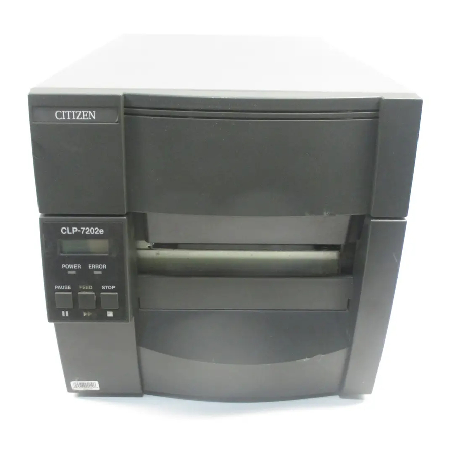
CLP-7201e
CLP-7202e
VAN MECHELEN
KANTOORMACHINES – KANTOORMATERIALEN
TURNHOUT –GEEL
www.vanmechelen.be
Advertisement
Table of Contents
Troubleshooting

Related Manuals for Citizen CLP-7201e


Summary of Contents for Citizen CLP-7201e
- Page 1 HALLE(KEMPEN) HALLE(KEMPEN) ZOERSEL LOENHOUT WUUSTWEZEL OVERPELT NEERPELT SINT-HUIBRECHT-LILLE LOMMEL ACHEL HAMONT HAMONT-ACHEL HECHTEL EKSEL HAM KWAADMECHELEN OOSTHout BOCHOLT KAULILLE REPPEL BEEK BREE GERDINGEN OPITTER TONGERLO(LIMB) LEOPOLDSBURC HEPPEN TESSENDERLO CROTE-BROGEL KLEINE-BROGEL PEER WIJCHMAAL LAAKDAL LAAKDAL CLP-7201e CLP-7202e VAN MECHELEN KANTOORMACHINES – KANTOORMATERIALEN TURNHOUT –GEEL...
-
Page 2: Before Operation
Before Operation FCC COMPLIANCE STATEMENT FOR AMERICAN USERS This equipment has been tested and found to comply with the limits for a Class A digital device, pursuant to Part 15 of the FCC Rules. These limits are designed to provide reasonable protection against harmful interference when the equipment is operated in a commercial environment. -
Page 3: Emi Compliance Statement For Canadian Users
Before Operation EMI COMPLIANCE STATEMENT FOR CANADIAN USERS This equipment generates and uses radio frequency energy and if not installed and used properly, that is, in strict accordance with the manufacturer's instructions, may cause interference to radio and television reception. This digital apparatus does not exceed the Class A limits for radio noise emissions from digital apparatus set out in the Radio Interference Regulations of the Canadian Department of Communications. -
Page 4: Important Safety Instructions
Before Operation Important Safety Instructions 1. Read all of these instructions and save them for later reference. 2. Follow all warnings and instructions marked on the product. 3. Unplug this product from the wall outlet before cleaning. Do not use liquid or aerosol cleaners. Use a damp cloth for cleaning. -
Page 5: Notice
Before Operation Notice 1. Before use, be sure to read this manual. And keep it handy for reference when needed. 2. The contents of this manual may change without prior notice. 3. Reproduction, transfer, or transmission of the contents of this manual without prior consent is strictly prohibited. -
Page 6: Safety Instructions
Before Operation... -
Page 7: Warning
Before Operation... -
Page 8: General Precautions
Before Operation General Precautions 1. Prior to operation, read the safety instructions carefully and observe them. 2. Do not drop or put foreign matter such as clips and pins into the printer. This may cause problems. 3. Be careful when moving or carrying the printer. Dropping the printer may cause injury or property damage. -
Page 9: Precautions When Installing The Printer
Before Operation Precautions When Installing the Printer 1. Prior to operation, read the safety instructions carefully and observe them. 2. Do not use or store the printer near fire, excessive moisture, in direct sunlight, near an air conditioner or heater or other source of unusually high or low temperature or humidity or excessive dust. -
Page 10: Table Of Contents
Before Operation Contents Before Operation FCC Compliance Statement for American Users----------------------------------------------1 Compliance Statement for European Users ----------------------------------------------------1 EMI Compliance Statement for Canadian Users ----------------------------------------------2 Important Safety Instructions -----------------------------------------------------------------------3 Notice ----------------------------------------------------------------------------------------------------4 Safety Instructions ------------------------------------------------------------------------------------5 Warning --------------------------------------------------------------------------------------------------6 General Precautions----------------------------------------------------------------------------------7 Precautions When Installing the Printer ---------------------------------------------------------8 Contents -------------------------------------------------------------------------------------------------9 Main Features ------------------------------------------------------------------------------------------11 Model Description -------------------------------------------------------------------------------------12... - Page 11 (Printhead Offset Adjustments) ------------------------------------------------------------ 48 2 Use of Narrow Media/Ribbons (Printhead Pressure Adjustments) -------------------------------------------------------- 49 3 Use of Narrow Media/Ribbons (Ribbon Tension Adjustments)--------------------- 50 4 Adjustable Sensor (For CLP-7201e) ----------------------------------------------------- 52 5 Cleaning ----------------------------------------------------------------------------------------- 53 Chapter 5 Troubleshooting 1 Error Messages-------------------------------------------------------------------------------- 56...
-
Page 12: Main Features
IC enables high-speed and high-quality printing. Powerful control language A powerful yet simple to use control language is standard to all of Citizen's label printers allowing easy design of labels and bar codes. Alternatively, Citizen provides printer drivers for popular operating systems such as Windows(tm). -
Page 13: Model Description
Model Description The following two models are available. The main different points between the two models are shown below. Adjustable Model Print resolution Printing speed Flash Memory media sensor CLP-7201e 200dpi 2−7 IPS Standard Standard on-board CLP-7202e 200dpi 2−7 IPS Optional... -
Page 14: Chapter 1 Setup
Chapter 1 Setup Chapter 1 Setup 1 Confirmation of Carton Contents 2 Part Names and Functions 3 Connection to Power 4 Connection to a Computer... -
Page 15: Confirmation Of Carton Contents
Chapter 1 Setup 1 Confirmation of Carton Contents 1 Confirmation of Carton Contents Check that the following accessories are included with the printer in the carton. The empty carton and packing materials should be stored for future shipping of the printer. CAUTION •... -
Page 16: Part Names And Functions
To attach the ribbon. (See Chapter 3.) Holds down the media. The adjustable, movable media sensor inside (available for (4) Ribbon winder the model CLP-7201e) detects the media To wind the ribbon after printing. position. (See Chapter 3.) (See Chapter 3.) - Page 17 Chapter 1 Setup 2 Part Names and Functions Side view (1) Adjust-screw To change the ribbon tension setting on the winding side. (See Chapter 4.) (2) Rear tension knob To change the ribbon tension setting on the feeding side. (See Chapter 4.) Rear view (1) Serial interface connector To connect the serial interface cable.
- Page 18 Chapter 1 Setup 2 Part Names and Functions Control panel (1) LCD (5) STOP key Displays the current printer status, Stops the printer operating. configuration settings, or an error message. (6) Media gap adjustment control (2) LEDs To adjust the media gap sensor sensitivity. One LED is the power indicator and the other (7) Black mark adjustment control the error indicator.
-
Page 19: Connection To Power
Chapter 1 Setup 3 Connection to Power 3 Connection to Power 1. Check that the power switch to the printer is turned OFF. 2. Connect the connector of the power cord to the power inlet on the printer. 3. Insert the plug of the power cord in the AC outlet. CAUTION •... -
Page 20: Connection To A Computer
Chapter 1 Setup 4 Connection to a Computer 4 Connection to a Computer An interface cable is necessary to connect the printer to a computer. To connect the cable, proceed as follows: 1. Turn OFF both power switches of the printer and the computer. 2. - Page 21 Chapter 1 Setup...
-
Page 22: Chapter 2 Printer Operation
Chapter 2 Printer Operation Chapter 2 Printer Operation 1 Power On/Off 2 Normal Operating Mode 3 Printer Configuration Setting Mode 4 Self-Test Mode & Hex Dump Mode 5 System Maintenance Mode 6 Returning to Factory Setting... -
Page 23: Power On/Off
Chapter 2 Printer Operation 1 Power On/Off 1 Power On/Off Turning on the power 1. Turn on the power switch on the back of the printer. 2. The green LED is lit. Check that the LCD screen displays 'On Line.'... - Page 24 Chapter 2 Printer Operation 1 Power On/Off Turning off the power 1. Turn off the power switch on the back of the printer. 2. The green LED goes off and any message on the LCD screen disappears.
-
Page 25: Normal Operating Mode
Chapter 2 Printer Operation 2 Normal Operating Mode 2 Normal Operating Mode When the power is turned on, the printer enters the normal operating mode, which allows normal printing. The control key functions are as follows: STOP key With this key, the operator can stop and cancel the current print job. -
Page 26: Printer Configuration Setting Mode
Chapter 2 Printer Operation 3 Printer Configuration Setting Mode 3 Printer Configuration Setting Mode In this menu, the print mode, the 'after printing function' such as cutting or peeling, media sensor selection and print quality settings such as print speed or density are configured. Control key functions are shown below. - Page 27 Chapter 2 Printer Operation 3 Printer Configuration Setting Mode 3. Change the media gap sensor to the black mark sensor with the FEED key. 4. Return to normal operating mode with the STOP key.
- Page 28 Chapter 2 Printer Operation 3 Printer Configuration Setting Mode Display Indications...
- Page 29 Chapter 2 Printer Operation 3 Printer Configuration Setting Mode List of Mode Items Note: When the printer is switched off and on, the initial values for these menu items selected by the printer configuration setting mode will be retrieved from the flash memory.
- Page 30 Chapter 2 Printer Operation 3 Printer Configuration Setting Mode Notes when setting print start position and media stop position • When the "AfterPnt" menu item is set to "AutoCut", the relation between print start position and media stop position should be set to [(O ( (f]. If the value is set so that [(O < (f], the media may be out of platen.
-
Page 31: Self-Test Mode & Hex Dump Mode
Chapter 2 Printer Operation 4 Self-Test Mode & Hex Dump Mode 4 Self-Test Mode & Hex Dump Mode In this mode, self-test printing is performed, and you can check the current printer configuration settings and print quality. After loading the media and ribbon, operate the printer in the following way: 1. - Page 32 Chapter 2 Printer Operation 4 Self-Test Mode & Hex Dump Mode Check the following items in the self-test mode. Check item Cause Remedy Dot missing Printhead disconnected Replace printhead Dust adhered Clean printhead (see Section 5, Chapter 4) Totally blurred Printhead offset changed in Adjust printhead offset position...
-
Page 33: System Maintenance Mode
Chapter 2 Printer Operation 5 System Maintenance Mode 5 System Maintenance Mode In system maintenance mode, the communication, adjustable sensor ON/OFF and sensor voltage selections are set up. The printer configuration settings are stored in memory so they are maintained even after the power is turned off. Control key functions are shown in the following: Example: Setting the black mark sensor voltage 1. - Page 34 Chapter 2 Printer Operation 5 System Maintenance Mode 3. Change the media gap sensor voltage to the black mark sensor voltage with the FEED key pressed. 4. Return to normal operating mode with the STOP key pressed.
- Page 35 Chapter 2 Printer Operation 5 System Maintenance Mode List of Mode Items Note: When the printer is switched off and on, the initial values for these menu items selected by the system maintenance mode will be retrieved from the flash memory.
-
Page 36: Returning To Factory Setting
Chapter 2 Printer Operation 6 Returning to Factory Setting 6 Returning to Factory Setting To return all the contents already made in the printer configuration setting mode or system maintenance mode to the factory setting, proceed as follows: First turn OFF the power switch, then press and hold the PAUSE, FEED and STOP keys simultaneously and at the same time turn ON the power switch, and continue holding down those keys. - Page 37 Chapter 2 Printer Operation...
-
Page 38: Chapter 3 Media And Ribbon
Chapter 3 Media and Ribbon Chapter 3 Media and Ribbon 1 Kinds of Approved Media 2 Configuration of Approved Media (When Using Front Sensors) 3 Configuration of Approved Media (When Using Adjustable Sensor) 4 Media Setting 5 Kinds of Approved Ribbons 6 Ribbon Setting... -
Page 39: Kinds Of Approved Media
Chapter 3 Media and Ribbon 1 Kinds of Approved Media 1 Kinds of Approved Media... -
Page 40: Configuration Of Approved Media (When Using Front Sensors)
Chapter 3 Media and Ribbon 2 Configuration of Approved Media (When Using Front Sensors) 2 Configuration of Approved Media (When Using Front Sensors) The front sensors consist of the transparent and reflective type photosensors that detect the position of the labels or tags: Transparent type photosensor: Detects gaps between labels and notches of tags. -
Page 41: Configuration Of Approved Media (When Using Adjustable Sensor)
3 Configuration of Approved Media (When Using Adjustable Sensor) 3 Configuration of Approved Media (When Using Adjustable Sensor) The adjustable sensor is the standard for CLP-7201e but it is the optional for CLP-7202e. Make sure that the adjustable sensor is set to 'AJSensON.' (See Chapter 2.) -
Page 42: Media Setting
Chapter 3 Media and Ribbon 4 Media Setting 4 Media Setting The printer is designed to easily load media. Open the printer cover and set media in the following: 1. Push down the open lever to open the printhead. 2. Push down the open guide lever to lift the open guide up. 3. - Page 43 Chapter 3 Media and Ribbon 4 Media Setting 4. (1) Push media against the fixed media guide on the left side. (2) Guide media positively with the movable media guide. (3) Align the left top edge of media with the notch of the tearing plate. 5.
-
Page 44: Kinds Of Approved Ribbons
Chapter 3 Media and Ribbon 5 Kinds of Approved Ribbons 5 Kinds of Approved Ribbons... -
Page 45: Ribbon Setting
Chapter 3 Media and Ribbon 6 Ribbon Setting 6 Ribbon Setting This printer is designed for easy ribbon loading. Open the printer cover and install the ribbon as follows: 1. Push down the open lever to open the printhead. 2. Insert the ribbon shaft in the core of ribbon so that it is in its deepest position. 3. - Page 46 Chapter 3 Media and Ribbon 6 Ribbon Setting 5. Wind the ribbon being pulled out around the ribbon holder and fix it to the core with adhesive tape. Set the ribbon holder on the transfer mechanism. Then turn its knob in the direction of arrow to remove the slack or wrinkle of the ribbon.
- Page 47 Chapter 3 Media and Ribbon...
-
Page 48: Chapter 4 Printer Adjustments
Printer Adjustments 1 Use of Media Other Than the Recommended (Printhead Offset Adjustments - Media Thickness Adjustments) 2 Use of Narrow Media/Ribbons (Printhead Pressure Adjustments) 3 Use of Narrow Media/Ribbons (Ribbon Tension Adjustments) 4 Adjustable Sensor (For CLP-7201e) 5 Cleaning... -
Page 49: Use Of Media Other Than The Recommended (Printhead Offset Adjustments)
Chapter 4 Printer Adjustments 1 Use of Media Other Than the Recommended (Printhead Offset Adjustments - Media Thickness Adjustments) 1 Use of Media Other Than the Recommended (Printhead Offset Adjustments - Media Thickness Adjustments) The printer is already factory-set to the requirements of proper print quality while using the recommended labels. -
Page 50: Use Of Narrow Media/Ribbons (Printhead Pressure Adjustments)
Chapter 4 Printer Adjustments 2 Use of Narrow Media/Ribbons (Printhead Pressure Adjustments) 2 Use of Narrow Media/Ribbons (Printhead Pressure Adjustments) The printer is already factory-set to the value of media width: 112 mm (4.4 in). When you use narrow media, adjust the printhead pressure in the following: 1. -
Page 51: Use Of Narrow Media/Ribbons (Ribbon Tension Adjustments)
Chapter 4 Printer Adjustments 3 Use of Narrow Media/Ribbons (Ribbon Tension Adjustments) 3 Use of Narrow Media/Ribbons (Ribbon Tension Adjustments) Ribbon tension of this printer is already adjusted to the recommended ink ribbon and media. Ribbon and media, however, may slip due to imperfect combination of ink ribbon and media, where a message 'RibonOut' will be shown on the LCD display. - Page 52 Chapter 4 Printer Adjustments 3 Use of Narrow Media/Ribbons (Ribbon Tension Adjustments) (2) Easy-to-slip ribbon and media If a message 'RibonOut' is shown, set the mark on the feeding section to LOW by turning the adjust-knob. (3) Especially-easy-to-slip ribbon and media If a message 'RibonOut' is still shown, although Step (2) has been performed, set...
-
Page 53: Adjustable Sensor (For Clp-7201E)
Chapter 4 Printer Adjustments 4 Adjustable Sensor (For CLP-7201e) 4 Adjustable Sensor (For CLP-7201e) Note: The adjustable sensor is optional for CLP-7202e. Operating procedure 1. Measure your required detection position beforehand, using the scale on the upper guide rail. Move the adjustable sensor to the required detection position by tuning the adjustable knob;... -
Page 54: Cleaning
Chapter 4 Printer Adjustments 5 Cleaning 5 Cleaning Wipe off any foreign matter such as ribbon or media dust, dirt and adhesive substances built up around the printhead, ribbon guide roller, platen etc with the accessory thermal head cleaner or a soft cloth soaked in ethyl alcohol. - Page 55 Chapter 4 Printer Adjustments...
-
Page 56: Chapter 5 Troubleshooting
Chapter 5 Troubleshooting Chapter 5 Troubleshooting 1 Error Messages 2 Power Troubleshooting 3 Media Feed Troubleshooting 4 Ribbon Feed Troubleshooting 5 Print Troubleshooting 6 Interface Troubleshooting... -
Page 57: Error Messages
Chapter 5 Troubleshooting 1 Error Messages 1 Error Messages When there is a problem with the printer: - A buzzer sounds. - The error indicator lights up. - An error message is shown on the LCD screen. Errors and corrective actions are shown below. 1 Errors indications... - Page 58 Chapter 5 Troubleshooting 1 Error Messages 2 Errors and corrective actions...
- Page 59 Chapter 5 Troubleshooting 1 Error Messages...
- Page 60 Chapter 5 Troubleshooting 1 Error Messages...
-
Page 61: Power Troubleshooting
Chapter 5 Troubleshooting 2 Power Troubleshooting 2 Power Troubleshooting... -
Page 62: Media Feed Troubleshooting
Chapter 5 Troubleshooting 3 Media Feed Troubleshooting 3 Media Feed Troubleshooting... -
Page 63: Ribbon Feed Troubleshooting
Chapter 5 Troubleshooting 4 Ribbon Feed Troubleshooting 4 Ribbon Feed Troubleshooting... -
Page 64: Print Troubleshooting
Chapter 5 Troubleshooting 5 Print Troubleshooting 5 Print Troubleshooting... -
Page 65: Interface Troubleshooting
Chapter 5 Troubleshooting 6 Interface Troubleshooting 6 Interface Troubleshooting... -
Page 66: Appendixes
Appendixes Appendixes 1 Options 2 Specifications... -
Page 67: Options
Appendixes 1 Options 1 Options Factory and dealer (reseller) options... - Page 68 Appendixes 1 Options User options Note: Some versions of this printer have flash memory installed on the main PCB as standard. You may not need to use a PCMCIA card in this case. Please contact the dealer from where you purchased the printer for further details. Installation 1.
-
Page 69: Specifications
Appendixes 2 Specifications 2 Specifications Main Specifications... - Page 70 Appendixes 2 Specifications...
- Page 71 Appendixes 2 Specifications...
- Page 72 Appendixes 2 Specifications Interfaces The printer is connected to a computer and prints labels according to the command from the computer. Two systems of interface connection to a computer are shown below. 1. Serial interface: RS-232C 2. Parallel interface: IEEE1284 compatible and nibble modes...
- Page 73 Appendixes 2 Specifications 3. USB Interface USB Interface Specifications USB1.1 4. RS-232C loopback test After connector wiring as shown in the figure, place the printer into self-test mode. The printer will receive data that has been transmitted by printer itself and the test of receiving and transmitting data will be performed.
- Page 74 Appendixes 2 Specifications 5. RS-232C protocol (1) X-ON/X-OFF system (see figure) This is a control system in which the data transmitting request signal (X-ON (11H) code) and the data transmitting stop signal (X-OFF (13H) code) are output. Requirements of output of X-ON code: •...
- Page 75 Appendixes 2 Specifications 6. Interface pin assignment The serial and parallel pin assignment tables are shown below. Serial interface pin assignment table...
- Page 76 Appendixes 2 Specifications Parallel interface pin assignment table...
- Page 77 Appendixes 2 Specifications Example of Connection to a Computer When RS-232C is used: (IBM PC compatible) Communication control: XON/XOFF or CTS/DTR...
- Page 78 Appendixes 2 Specifications Tear-Off Function The tear-off function eliminates the waste of labels when tearing manually. It allows media to automatically advance to the tear position after printing. When this function is turned on, media will be fed to the manual tear position after printing. The printer will feed back media to the start print position when the next print job is sent.
- Page 79 Appendixes 2 Specifications 2. Tear-off when printing • If set, the tear-off feature will start if no data is transmitted from the computer after printing. If data is transmitted continuously from the computer, the tear-off function will be suppressed. Tear-off is only performed for the final label of each batch processing.
- Page 80 Appendixes 2 Specifications 3. Tear-off when feeding • Media are fed to the tear position. • When the manual tearing is needed, tear the label at this time. • Perform next feeding or label printing. If the Feed key is pressed or next print data is transmitted from the computer, the printer will feed back media to the previous print completed position and resume feeding or printing.
- Page 81 Appendixes 2 Specifications Cut Position Adjustments • The cut position can be specified with the 'fnnn' of the system-level commands. When the tear-off function is turned on, the following initialization value is set in the printer. Initialization value: fnnn = f735 (73.5 mm) The values higher or lower will increase or decrease the amount of feed in the tear-off.
- Page 82 Citizen America Corporation 831 S. Douglas Street, Suite 121 El Segundo, CA 90245 Tel: (310) 643-9825 U.S.A. Citizen Systems Europe GmbH http://www.citizen-europe.com Mettinger Strasse 11 Park House 73728 Esslingen 643-651 Staines Road, Feltham Germany Middlesex, TW14 8PA United Kingdom Japan CBM Corporation CBM Bldg., 5-68-10, Nakano...
Need help?
Do you have a question about the CLP-7201e and is the answer not in the manual?
Questions and answers