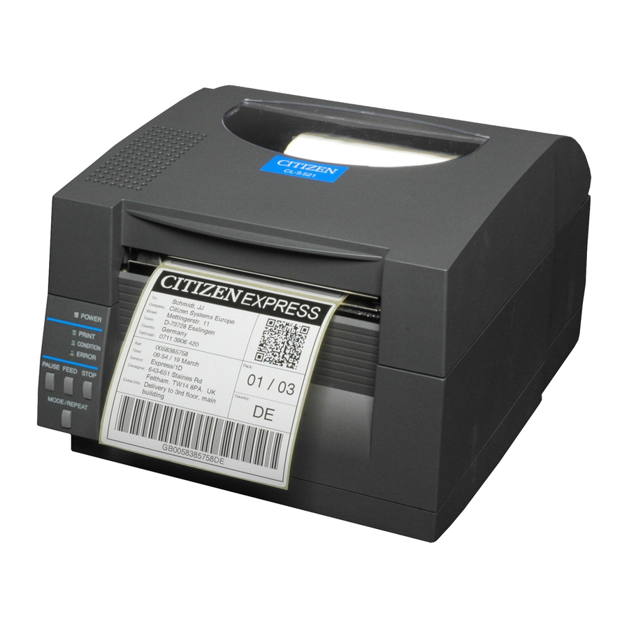
Citizen CL-S521 User Manual
Thermal label & barcode printer
Hide thumbs
Also See for CL-S521:
- User manual (66 pages) ,
- Quick start manual (4 pages) ,
- Features & specifications (2 pages)
Table of Contents
Advertisement
Advertisement
Table of Contents

Related Manuals for Citizen CL-S521


Summary of Contents for Citizen CL-S521
- Page 1 Thermal Label & Barcode Printer CL-S521 & CL-S531 SER'S ANUAL...
-
Page 2: Table Of Contents
CONTENTS Before Operation INTRODUCTION..........................3 COMPLIANCE.STATEMENT.FOR.EUROPEAN.USERS............4 GS.MARK.STATEMENT........................4 FCC.COMPLIANCE.STATEMENT.FOR.AMERICAN.USERS............ 4 EMI.COMPLIANCE.STATEMENT.FOR.CANADIAN.USERS............ 5 ETAT.DE.CONFORMITE.EMI.A.L’USAGE.DES.UTILISATEURS.CANADIENS..... 5 IMPORTANT.SAFETY.INSTRUCTIONS..................6 NOTICE..............................7 SAFETY.INSTRUCTIONS......................... 8 Chapter 1 Setup Confirmation.of.Carton.Contents...................10 Part.Names.and.Functions......................11 Connection.to.Power........................16 Driver.Installation.........................16 Connection.to.a.Computer......................17 Chapter 2 Printer Operation Power.ON/OFF..........................18 Normal.Operating.Mode. -
Page 3: Introduction
INTRODUCTION Thank.you.very.much.for.purchasing.Citizen’s.compact.direct.thermal.label.&.barcode.printer.Model.CL-S521/ CL-S531.that.offers.high.performance.printing.at.6.inches/4.inches.per.second.on.4.1.inch.media.at.very.low. cost. ■■■ ■■■ Main Features <High-speed, high-quality printing> This.printer.can.be.used.for.high-speed.high-quality.printing.thanks.to.its.thermal-transfer.system. that.uses.a.line.thermal.printhead.together.with.its.32.bit.RISC.CPU.and.its.‘history.control.IC’ . <Easy operation> . • It.is.easy.to.change.the.printer’s.settings.on.the.operation.panel,.thanks.to.its.unique.and. simple.VuePrint.menu.system. . • Its.high-lift.printhead.and.mechanism.means.that.media.can.be.loaded.with.ease.and.it.is. constructed.for.easy.thermal.printhead.cleaning,.etc. . • Media.width.adjustment,.media.thickness.adjustment,.and.media.sensor.adjustment.can. all.be.made.easily.by.the.user.using.the.colour-coded.operator.controls. <Dual Programming Language> This.printer.contains.both.the.Datamax®.and.Zebra®.emulations.and.will.automatically. detect.the.language.using.the.Cross-Emulation .feature. <Interface> An.industry.standard.RS232.serial.port.and.USB1.1.port.are.standard.equipment,.for.quick. data.transfer.and.printing. <Optional interface> Additional.connectivity.is.available.with.an.optional.internally-housed.IEEE1284.parallel.port,. -
Page 4: Compliance.statement.for.european.users
COMPLIANCE STATEMENT FOR EUROPEAN USERS CE.marking.shows.conformity.to.the.following.criteria.and.provisions: Low.Voltage.Directive.(2006/95/EC,.formerly.73/23/EEC)/EN60950-1 EMC.Directive.(2004/108/EC,.formerly.89/336/EEC)/EN55022,.EN55024,.EN61000-3-2.& EN61000-3-3 GS MARK STATEMENT This.product.has.been.tested.under.EN.ISO.7779.and.has.an.acoustic.level.output.no.higher.than 55db(A). This.device.is.not.intended.for.use.at.a.video.workstation.in.compliance.with.Bildscharb.V. This.device.is.not.intended.for.use.in.the.direct.field.of.view.at.visual.display.workplaces..To.avoid. incommoding.reflections.at.visual.display.workplaces.this.device.must.not.be.placed.in.the.direct. field.of.view. FCC COMPLIANCE STATEMENT FOR AMERICAN USERS This.equipment.has.been.tested.and.found.to.comply.with.the.limits.for.a.Class.A.digital.device,. pursuant.to.Part.15.of.the.FCC.Rules..These.limits.are.designed.to.provide.reasonable.protection. against.harmful.interference.when.the.equipment.is.operated.in.a.commercial.environment.. This.equipment.generates,.uses,.and.can.radiate.radio.frequency.energy.and,.if.not.installed. and.used.in.accordance.with.the.instruction.manual,.may.cause.harmful.interference.to.radio. communications. Operation.of.this.equipment.in.a.residential.area.is.likely.to.cause.harmful.interference.in.which. case.the.user.will.be.required.to.correct.the.interference.at.his.own.expense. *.The.model.name.printed.on.the.CL-S521.rating.label.is.JM30-M01. . The.model.name.printed.on.the.CL-S531.rating.label.is.JM33-M01. -
Page 5: Emi.compliance.statement.for.canadian.users
EMI COMPLIANCE STATEMENT FOR CANADIAN USERS This Class A digital apparatus complies with Canadian ICES-003. This. equipment. generates. and. uses. radio. frequency. energy. and. if. not. installed. and. used. properly,.that.is,.in.strict.accordance.with.the.manufacturer’s.instructions,.may.cause.interference. to.radio.and.television.reception..This.digital.apparatus.does.not.exceed.the.Class.A.limits.for. radio.noise.emissions.from.digital.apparatus.set.out.in.the.Radio.Interference.Regulations.of.the. Canadian.Department.of.Communications..This.equipment.is.designed.to.provide.reasonable. protection.against.such.interference.in.a.residential.installation..However,.there.is.no.guarantee. that. interference. will. not. occur. in. a. particular. installation.. If. this. equipment. does. cause. interference.to.radio.or.television.reception,.which.can.be.determined.by.turning.the.equipment. -
Page 6: Important.safety.instructions
IMPORTANT SAFETY INSTRUCTIONS •. Read.all.of.these.instructions.and.save.them.for.later.reference. •. Follow.all.warnings.and.instructions.marked.on.the.product. •. Unplug.this.product.from.the.wall.outlet.before.cleaning..Do.not.use.liquid.or.aerosol.cleaners..Use.a. damp.cloth.for.cleaning. •. Do.not.use.this.product.near.water. •. Do.not.place.this.product.on.an.unstable.cart,.stand.or.table..The.product.may.fall,.causing.serious. damage.to.the.product. •. Slots.and.openings.on.the.cabinet.and.the.back.or.bottom.are.provided.for.ventilation. . To.ensure.reliable.operation.of.the.product.and.to.protect.it.from.overheating,.do.not.block.or.cover.these. openings..The.openings.should.never.be.blocked.by.placing.the.product.on.a.bed,.sofa,.rug.or.other. similar.surface..This.product.should.never.be.placed.near.or.over.a.radiator.or.heat.register..This.product. should.not.be.placed.in.a.built-in.installation.unless.proper.ventilation.is.provided. •. This.product.should.be.operated.from.the.type.of.power.source.indicated.on.the.marking.label. . If.you.are.not.sure.of.the.type.of.power.available,.consult.your.dealer.or.local.power.company. •. This.product.is.equipped.with.a.three-pronged.plug,.a.plug.having.a.third.(grounding).pin..This.plug.will. only.fit.into.a.grounding-type.power.outlet..This.is.a.safety.feature..If.you.are.unable.to.insert.the.plug.into. the.outlet,.contact.your.electrician.to.replace.your.obsolete.outlet..Do.not.defeat.the.safety.purpose.of.the. grounding-type.plug. •. Do.not.allow.anything.to.rest.on.the.power.cord..Do.not.locate.this.product.where.the.cord.will.be.walked. •. If.an.extension.cord.is.used.with.this.product,.make.sure.that.the.total.of.the.ampere.ratings.on.the. products.plugged.into.the.extension.cord.do.not.exceed.the.extension.cord.ampere.rating..Also,.make. sure.that.the.total.of.all.products.plugged.into.the.wall.outlet.does.not.exceed.15.amperes.for.120V.outlet. and.7.5.amperes.for.220V-240V.outlet. •. Never.push.objects.of.any.kind.into.this.product.through.cabinet.slots.as.they.may.touch.dangerous. voltage.points.or.short.out.parts.that.could.result.in.a.risk.of.fire.or.electric.shock..Never.spill.liquid.of.any. -
Page 7: Notice
•. We. are. not. liable. for. any. damage. caused. by. user's. erroneous. use. of. the. printer. and. inadequate. environment. •. Data.residing.in.the.printer.is.temporary..Therefore,.all.data.will.be.lost.if.power.is.lost..We.are.not.liable.for. any.damage.or.loss.of.profits.caused.by.data.loss.due.to.failures,.repairs,.inspections,.etc. •. Please.contact.us.if.there.are.any.mistakes.or.ambiguities.within.this.manual. •. If.there.are.missing.or.incorrectly.collated.pages.in.this.manual,.contact.us.to.obtain.a.new.manual. CITIZEN is a registered trademark of CITIZEN HOLDINGS CO., Japan. CITIZEN es una marca registrada de CITIZEN HOLDINGS CO., Japón. Copyright © 2012 by CITIZEN SYSTEMS JAPAN CO., LTD. -
Page 8: Safety.instructions
SAFETY INSTRUCTIONS which must be strictly observed ! • To prevent personal injury or property damage, the following shall be strictly observed. • The degree of possible injury and damage due to incorrect use or improperly following instructions is described below. Indicates a situation which, if not observed and handled Warning properly, could result in death or serious injury. -
Page 9: General Precautions
General Precautions Caution •. Prior.to.operation,.read.the.safety.instructions.carefully.and.observe.them. •. Do.not.drop.or.put.foreign.matter.such.as.clips.and.pins.into.the.printer..This.may.cause.problems. •. Be.careful.when.moving.or.carrying.the.printer..Dropping.the.printer.may.cause.injury.or.property. damage. •. Make.sure.if.you.open.the.top.cover,.it.is.opened.all.the.way..If.only.partially.open,.the.cover.could. slam.shut,.possibly.causing.injury. •. When.the.cover.is.open,.be.careful.of.the.corners.of.the.cover..They.could.cause.injury. •. Do.not.open.the.printer.during.printing. •. When.cleaning.the.surface.of.the.printer.case,.do.not.use.the.cloth.that.is.soaked.in.thinner,. trichloroethylene,.benzine,.ketone.or.similar.chemicals. •. Do.not.use.the.printer.where.there.is.a.lot.of.oil,.iron.particles,.or.dust. •. Do.not.spill.liquids.or.spray.insecticide.on.the.printer. •. Do.not.jolt.or.impact.to.the.printer.by.stepping.on,.dropping.or.hitting.the.printer. •. Operate.the.control.panel.properly..A.careless,.rough.handling.may.cause.problems.or.malfunction.. Do.not.use.such.sharp-edged.tool.as.a.ballpoint.pen.for.operation. •. Be.careful.of.the.edges.of.the.plates.so.injury.or.property.damage.is.possible. •. If.a.problem.occurs.during.printing,.stop.the.printer.immediately.and.unplug.the.power.cord.from. the.outlet. •. When.printer.trouble.occurs,.do.not.try.to.dissemble.it..Instead,.consult.our.service.personnel. Precautions When Installing the Printer Caution •. -
Page 10: Chapter 1 Setup
Chapter 1 Setup Chapter 1 Setup Confirmation of Carton Contents Removing the Packing Material The.printer.is.shipped.with.adhesive.tape.in.place.to.hold.the.top.cover. closed...Simply.remove.the.two.pieces.of.tape.on.either.side.of.the.top. cover..Then.simply.open.the.cover.by.lifting.up.and.tipping.it.backwards. There.is.another.strip.of.adhesive.tape.that.must.be.removed.which.holds. the.mechanism.closed.for.shipping...Remove.the..tape.and.attached. paper.by.carefully.peeling.from.the.plastic.case. Retain.the.tape.should.you.need.to.transport.the.printer.again.. Check that the following accessories are included with the printer in the carton. Media holder Media holder Head cleaner guide Power cord Test label media... -
Page 11: Part.names.and.functions
Chapter 1 Setup Caution . • Be.careful.when.moving.or.carrying.the.printer.and.when.taking.the. printer.out.of.the.carton..The.printer.may.cause.injury.or.property. damage.if.dropped..Be.sure.to.grip.the.printer.housing.firmly.when. taking.it.out.of.the.carton..Do.not.grip.the.printer.by.the.foam. packing.material.which.may.break,.causing.the.printer.to.drop. . • When.opening.the.cover,.open.it.all.the.way..If.only.part.way. open,.the.cover.could.slam.shut,.possibly.causing.injury. . • Be.careful.of.the.edge.of.the.cover.when.the.cover.is.opened..It. may.cause.injury.or.property.damage. . • Be.careful.of.the.edges.of.the.metal.plates.so.injury.or.property. damage.is.possible. Part Names and Functions Front View 1 Top cover Is.opened.vertically.to.place.or.replace.media. 2 Heat discharge vent It.allows.warm.air.to.vent.from.the.printer. Be.sure.not.to.block.it.with.media.etc. Operation Panel (p.14) 3 Operation panel This.is.used.to.make.changes.and.adjustments.to.the.printer.and.its. - Page 12 Chapter 1 Setup Part Names and Functions 5 Media holder bar The.media.is.supported.by.the.media.holder.bar.when.installed.in.the. printer. 6 Media holder guide This.guide.is.moved.horizontally.to.match.the.media.size... The.guide.can.be.sliding.it.from.the.holder.bar. 7 Motor cover It.discharges.the.heat.of.the.media.feed.motor... Do.not.cover.it.with.media.etc. 8 Front cover It.is.removed.to.install.optional.units.such.as.the.peeler.or.cutter. 9 Media width adjustment dial Media Width Adjustment (p.43) It.is.adjusted.to.match.the.width.of.the.media. a Media thickness adjustment dial Media Thickness Adjustment (p.42) It.is.adjusted.to.match.the.thickness.of.the.media.
- Page 13 Chapter 1 Setup Part Names and Functions c Thermal printhead This is the printhead. Avoid touching this with your fingertips and leaving grease or dirt on the printhead surface. d Platen Interlocked with the thermal printhead, it feeds media backwards or forwards.
-
Page 14: Operation Panel
Chapter 1 Setup Part Names and Functions Operation Panel LED Functions (p.20) 1 POWER LED This.is.lit.when.the.printer.power.is.on..(green) 2 PRINT LED This.is.lit.when.the.printer.is.able.to.print..(green) 3 CONDITION LED This.is.on.when.selecting.settings..(orange) 4 ERROR LED This.is.lit.or.flashes.when.the.printer.is.in.an.alarm.or.error.status..(red) 5 PAUSE key Normal Operating Mode (p.19) This.temporarily.stops.printing. 6 FEED key This.key.feeds.the.media.to.the.top.of.the.next.label.or.form. 7 STOP key This.stops.printing.or.cancels.the.alarm. -
Page 15: Rear View
Chapter 1 Setup Part Names and Functions Rear View 1 Serial interface (RS232C) Serial Interface (p.51) This.receives.serial.transmission.of.data.from.a.host.computer. 2 USB interface USB Interface (p.53) This.receives.USB.transmission.of.data.from.a.host.computer. 3 Power switch Power ON/OFF (p.18) The.is.the.power.switch.for.the.printer. 4 Power cord inlet Connection to Power (p.16) The.connector.of.the.enclosed.power.cord.is.connected.here. -
Page 16: Connection.to.power
Chapter 1 Setup Connection to Power 1. Check that the power switch to the printer is turned OFF. 2. Connect the connector of the power cord to the power cord inlet on the printer. 3. Insert the plug of the power cord in the AC outlet. Power Switch AC Outlet Power Cord Inlet Caution Use.an.AC.outlet.that.accepts.a.three-pronged.plug..Otherwise,. static.electricity.may.be.generated.and.there.will.be.danger.of. electric.shock. Driver Installation The.computer.may.automatically.detect.the.presence.of.the.new.printer. when.it.is.first.started,.depending.on.the.computer.type,.interface.and. operating.system...Follow.any.on-screen.instruction.and.also.instructions. supplied.with.any.additional.CD-ROM.or.floppy.disk.included.with.your. printer. Your.supplier.will.assist.you.with.the.correct.drivers.and.software.which. are.compatible.with.your.particular.computer.system. -
Page 17: Connection.to.a.computer
Chapter 1 Setup Connection to a Computer This.product.has.two.interfaces.that.can.be.used.to.receive.printing. data:.a.serial.port.(RS232C).and.a.USB.port.(USB1.1)..An.optional.internal. Ethernet,.an.IEEE1284.Parallel.or.Wireless.LAN.port.can.be.added.by.your. dealer. With.the.exception.of.a.wireless.LAN.connection,.an.interface.cable.is. necessary.to.connect.the.printer.to.a.computer. To.connect.the.cable,.proceed.as.follows: 1. Turn OFF both power switches of the printer and the computer. 2. Connect one end of the interface cable to the interface connector on the back of the printer and secure it with locks or locking screws, where available. 3. Connect the other end of the interface cable to the interface connector on the computer and secure it with locks or locking screws, where available. Serial Interface (p.51) USB Interface (p.53) Serial Interface Cable USB Interface Cable Note:. If.the.optional.Ethernet,.an.IEEE1284.Parallel.or.Wireless.LAN.port. is.used,.contact.your.Citizen.Systems.dealer. -
Page 18: Chapter 2 Printer Operation
Chapter 2 Printer Operation Chapter 2 Printer Operation Power ON/OFF Turning on the power 1. Turn on the power switch on the back of the printer. 2. The POWER and PRINT LED are lit. Operation Panel Power Switch Turning off the power 1. Turn off the power switch on the back of the printer. 2. The POWER and PRINT LED go off. Power Switch... -
Page 19: Normal.operating.mode
Chapter 2 Printer Operation Normal Operating Mode Menu Setup Mode (p.27) When.the.power.is.turned.on,.the.printer.enters.normal.operating.mode.. The.control.keys.activate.the.following.functions. 1 PAUSE key: Temporarily pauses printing . • When.this.key.is.pushed.once,.the.PRINT.LED.turns.off.and.the. printer.temporarily.pauses.. . • When.it.is.pushed.during.printing,.the.printer.pauses.after.the.label. currently.being.printed.is.issued..Pressing.the.key.a.second.time. restarts.printing.and.the.remaining.number.of.designated.labels.are. printed. 2 FEED key: Feeds media . • Pressing.this.key.feeds.media.to.the.print.start.position..The.distance. it.is.fed.is.determined.by.automatically.detecting.the.front.end.of. the.media.when.using.label.media,.and.when.continuous.media.has. been.designated,.a.fixed.quantity.is.fed,.then.feeding.stops. . - Page 20 Chapter 2 Printer Operation Normal Operating Mode LED Functions In.addition.to.normal.operating.mode,.when.an.abnormal.condition.is. detected.in.the.printer,.an.alarm.sounds.and.each.LED.either.lights.up.or. flashes.to.indicate.the.type.of.error. 1 POWER LED It.lights.up.when.printer.power.is. turned.on..(green) 2 PRINT LED This.is.lit.when.the.printer.is.able.to. print..(green) 3 CONDITION LED This.is.on.when.selecting.settings.. (orange) 4 ERROR LED This.is.lit.or.flashes.when.the.printer.is. in.error.status..(red) Table of Alarm and Error Indications CONDITION Item PRINT.LED ERROR.LED When.the.STOP.key.has.been.pushed...
-
Page 21: Setting.the.media
Chapter 2 Printer Operation Setting the Media Media Sizes The.position.of.label.and.tag.media.is.sensed.by.either.a.transparent. sensor.or.a.reflective.sensor. Transparent.sensor:. Detects.the.gaps.between.label.media.and.notches. of.tag.media Reflective.sensor:.. Detects.the.black.mark Continuous media Label media Notch detection Black mark detection Label Printed area Label Label Transparent sensor Re ective sensor Media direction Min..value.mm.(inches) Max..value.mm.(inches) Label.width 19.50.(0.77) 118.00.(4.65) Liner.width... - Page 22 Chapter 2 Printer Operation Setting the Media Installing the Media 1. Push the large blue-head open lever to release the head unit and sensor arm. It can be opened to the position shown below by lifting the head unit by hand. Large blue-head open lever 2. Firstly, slide the two black plastic parts of the media holder assembly together. Ensure correct alignment of the guide with the bar as it can only be installed in one direction. 3. Slide the roll of media over the media bar. The media guide must be on the right side of the roll of media (as viewed from the front of the printer) with the ribbed surface of the media guide touching the media roll as shown in the illustration. Media holder guide Media holder bar 4. Set the media roll and media holder in to the printer as shown Media Sizes (p.21) above. It is advisable to pull a length of media forwards and through the mechanism ready for later positioning. 5. Move the media roll so it is touching the leftside of the housing. Then slide the black media guide so it is touching the media on the right side. Do not try to hold the media...
- Page 23 Chapter 2 Printer Operation Setting the Media Sensor Selection Method 6. Setting sensor positions. (Transparent Reflective) (p.39) When using a transparent sensor Adjusting the Transparent sensor Move.the.bottom.sensor.close.to.the.center.of.the.width.of.the.media,. (p.40) then.align.the.upper.sensor.marker.and.the.bottom.sensor.marker. (white).using.the.movable.media.guide. When.using.media.that.is.4.inches.wide,.position.the.upper.sensor. and.the.bottom.sensor.all.the.way.to.the.right.(large.blue-head.open. lever.side). Upper sensor marker Upper sensor Aligned with the marker Bottom sensor Transparent sensor marker...
- Page 24 Chapter 2 Printer Operation Setting the Media 7. Align the media with the left fixed media guide, align the right movable media guide with the media width, and lower the sensor arm. Movable media Fixed media guide guide Sensor arm 8. Lower and lock the head unit. Align it with the width of Media Thickness Adjustment (p.42) the media that has been set, then set the media width and Media Width Adjustment (p.43) media thickness adjustment dials. See “Chapter 3 Printer Adjustments”. Head unit Media thickness adjustment Media width adjustment 9. With the power switched on, push the FEED key to feed the media.
-
Page 25: Mode.settings
Chapter 2 Printer Operation Mode Settings Operation Panel (p.14) Turning.on.the.power.while.pressing.keys.in.the.following.combinations. starts.various.functions. Mode Key operation HEX.dump.mode Turning.power.on.while.pushing.the.STOP.key. Self.print.mode Turning.power.on.while.pushing.the.FEED.key. Menu.setting.mode Turning.power.on.while.pushing.the.MODE/REPEAT.key. HEX Dump Mode When using label media Turn.on.printer.power.while.pushing.the.STOP.key..If.the.PRINT.LED. has.begun.to.flash.slowly,.release.the.STOP.key,.and.then.the.printer. enters.HEX.DUMP.mode. When using continuous media Turn.on.printer.power.while.pushing.the.STOP.key..If.the.PRINT.LED. has.stopped.flashing.slowly.and.begun.to.flash.rapidly,.release.the. STOP.key,.and.then.the.printer.enters.HEX.dump.mode. DUMP LIST... - Page 26 Chapter 2 Printer Operation Mode Settings Self Print Mode Performing a self test print is an easy way to check on the state of printer setting and printing quality. Install the media as explained in “Installing the Media” and then operate the printer as follows. ...
- Page 27 Chapter 2 Printer Operation Mode Settings Menu Setup Mode If.the.printer.power.is.turn.on.while.the.MODE/REPEAT.key.is.pressed,.the. printer.enters.menu.setup.mode..In.this.mode,.the.printer’s.configuration. can.be.changed.using.the.VuePrint.Menu.System...During.menu.setting. mode,.the.PRINT.LED.and.CONDITION.LED.are.on...Media.must.be. installed.in.the.printer.to.use.the.VuePrint.menu.system. Light up YES/Select/Save NO/Next Item/Change Value Next digit Exit to previous menu Functions of the keys After.each.menu.item.is.printed,.the.printer.will.also.print.the.function. of.each.of.the.buttons.at.that.time...They.vary.slightly.depending.on.the. menu.selected.but.generally.fit.the.following..guidelines: PAUSE key (YES/Select/Save): It.is.pushed.to.either.select.the.current.menu.option.or.to.save.the. new.setting.after.which.it.advances.to.the.next.menu. STOP key (NO/Next Item/Change Value): Whilst.changing.a.menu.value.(such.as.head.temperature),.pressing.
- Page 28 Chapter 2 Printer Operation Mode Settings [Datamax® Emulation] Menu Setting Flow Chart The.following.is.a.flow.chart.showing.the.CL-S521/CL-S531.VuePrint.menu.system. Datamax® Emulation Operation Panel Menu Setup Mode (p.27) MODE/REPEAT key + Power on Press FEED key for 3 seconds Do you Printing during top menu Initialization of the...
- Page 29 Chapter 2 Printer Operation Mode Settings [Zebra® Emulation] Zebra® Emulation Operation Panel Menu Setup Mode (p.27) MODE/REPEAT key + Power on Press FEED key for 3 seconds Do you Printing during top menu Initialization of the EXIT want to reset this content of the settings setting (p.30) Are you sure?
- Page 30 Mode Settings Shown.below.is.a.sample.menu.output.from.the.VuePrint.menu.system.. This.particular.example.is.changing.the.print.speed.and.print.darkness. then.continues.through.the.remainder.of.the.“Print.Setup”.menu. The.actual.output.from.the.printer.is.“vertically.reversed”.due.to.the.way. the.printer.outputs.the.menu.options..Please.look.at.the.example.below. to.see.how.the.output.changes. Printing during top menu setting Menu Setting Flow Chart (p.28) <Example of CL-S521 Datamax® emulation selected> Printing during sub menu setting Menu Setting Flow Chart (p.28) <Example of CL-S521 Datamax® emulation selected>...
-
Page 31: Mode Settings
RS-232C Length : 8 bit RS-232C Stop bit : 1 bit RS-232C X-ON : Yes IEEE 1284 : On USB Device Class : Printer USB VCOM Protocol : Auto <Example of CL-S521 Datamax® emulation selected> *.. The.settings.of.the.Symbol.Set.can.be.changed.only.by.a.command. Note:. Citizen.continually.enhances.its.printers.with.new.options.and. settings.based.on.our.customer’s.requests..Extra.or.changed.menu. items.may.appear.on.the.above.print.out.in.some.case. - Page 32 Datamax® Emulation Top Menu Sub Menu Default Menu Remarks Global – Config.Set.1 Config.Set.1 Sets.the.Config.Set. configuration Config.Set.2 Config.Set.3 Page Setup Print.Speed 4.IPS 2.to.6.IPS [For.CL-S521] Printing.speed.setting. (2.to.4.IPS.with.optional.peeler.) 4.IPS 2.to.4.IPS [For.CL-S531] Printing.speed.setting. Print.Darkness 00.to.30 Print.darkness.setting. (printhead.temperature) Darkness.Adjust -10.to.10 Darkness.command.adjustment Continuous.Media. 4.00.inch 0.25.to.32.00.inch Setting.default.length.of.continuous.media,.
- Page 33 Chapter 2 Printer Operation Mode Settings [Datamax® Emulation] Top Menu Sub Menu Default Menu Remarks Settings.Lock When.on,.prevents.software.commands. from.changing.the.values.set.by.the.VuePrint. menu Keyboard.Lock Prevents.the.control.panel.from.affecting. the.printer’s.configuration..(User.“lock-out”) Control.Code Selects.between.the.Standard.STX.control. code.or.the.“Alternative”.code..Sometimes. ALT-2 called.“AS400.mode”. Emulation.Select Selects.DataMax®/Zebra®.compatibility DMI:.DataMax®.IClass DM4:.DataMax®.400.like ZPI2 DPP:.DataMax®.Prodigy.Plus® ZPI2:.Zebra®.Emulation Emulation.Auto. Selects.the.detection.of.Datamax®.and. Detect Zebra®.emulation. Full.Auto After Print AutoConfigure Optional.auto.configure On.
- Page 34 Chapter 2 Printer Operation Mode Settings [Datamax® Emulation] Top Menu Sub Menu Default Menu Remarks Mode/Repeat.Key Disabled LabelSet Repeat.method.selection LastOne LabelSet: Disabled Reissues.multiple.labels. LastOne: Issues.only.the.final.page.. In.count.case,.it.issues.only.1.label.while. .. continuing. Disabled: Makes.the.repeat.key.invalid. Interface RS-232C.Baud 9600 115200 Sets.the.baud.rate.of.the.serial.interface. 57600 •.Interface.related.settings.are.effective.after. 38400 the.power.is.turned.on.again. 19200 9600 4800 2400...
- Page 35 Zebra® Emulation Top Menu Sub Menu Default Menu Remarks Global – Config.Set.1 Config.Set.1 Sets.the.Config.Set. configuration Config.Set.2 Config.Set.3 Page Setup Print.Speed 4.IPS 2.to.6.IPS [For.CL-S521] Printing.speed.setting. (2.to.4.IPS.with.optional.peeler.) 4.IPS 2.to.4.IPS [For.CL-S531] Printing.speed.setting. Print.Darkness 00.to.30 Print.darkness.setting. (printhead.temperature) Darkness.Adjust -10.to.10 Darkness.command.adjustment Continuous.Media. 4.00.inch 0.25.to.32.00.inch Setting.default.length.of.continuous.media,.
- Page 36 Chapter 2 Printer Operation Mode Settings [Zebra® Emulation] Top Menu Sub Menu Default Menu Remarks Emulation Select ZPI2 Selects DataMax®/Zebra® compatibility DM4: DataMax® 400 DMI: DataMax® IClass ZPI2 DPP: DataMax® Prodigy Plus® ZPI2: Zebra® Emulation Emulation Auto Selects the detection of Datamax® and Detect Zebra®...
- Page 37 Chapter 2 Printer Operation Mode Settings [Zebra® Emulation] Top Menu Sub Menu Default Menu Remarks Interface RS-232C.Baud 9600 115200 Sets.the.baud.rate.of.the.serial.interface. 57600 •.Interface.related.settings.are.effective.after. 38400 the.power.is.turned.on.again. 19200 9600 4800 2400 RS-232C.Parity None None Sets.the.communication.parity.of.the.serial. interface. Even RS-232C.Length 8.bits 8.bits Sets.the.character.length.of.the.serial. 7.bits interface. RS-232C.Stop.bit 1.bit 1.bit...
-
Page 38: Emulation.auto.detect:.cross-Emulation Tm
Chapter 2 Printer Operation Emulation Auto Detect: Cross-Emulation A different emulation will be detected when the Emulation Auto Detect Menu Setting Table (p.33, p.36) of the System Setup is set to On or Full Auto. (Detects Zebra® when Datamax® is selected, and Datamax® when Zebra® is selected.) If the “Emulation Auto Detect”... -
Page 39: Chapter 3 Printer Adjustments
Chapter 3 Printer Adjustments Chapter 3 Printer Adjustments Sensor Adjustments The.sensing.level.of.both.the.transparent.(see.thru).and.reflective.sensors. is.adjusted.separately.and.independently..Firstly,.the.sensor.type.must. be.selected.either.using.the.VuePrint.menu.system.or.the.Sensor.Method. Selection.shown.below..Then.the.adjustment.and.calibration.of.the.sensor. can.be.made. Entering Sensor Adjustment Mode 1. Turn on the power while pushing the PAUSE key, FEED key, and STOP key simultaneously. Power Switch 2. After the PRINT LED and CONDITION LED light up, release the keys to change the printer to sensor adjustment setting mode. Sensor Selection Method (Transparent Reflective) Installing the Media (p.24) To.switch.from.transparent.to.reflective.sensor,.ensure.the.CONDITION. LED.is.lit.then.hold.down.the.MODE/REPEAT.key.and.then.press.the.STOP. key..Each.time.you.press.the.STOP.key,.you.switch.to.back.and.forth. between.the.two.sensor.types. - Page 40 Chapter 3 Printer Adjustments Sensor Adjustments Adjusting the Transparent sensor Installing the Media (p.24) 1. Push the large blue-head open lever to open the head unit and sensor arm, then return only the sensor arm to its original position. Align the upper sensor marker and the bottom sensor marker (white) using the movable media guide. Upper sensor marker Upper sensor Alignment of markers Bottom sensor Transparent sensor marker Movable media guide 2. Select the transparent sensor, and open the sensor arm. Sensor Selection Method (Transparent ...
- Page 41 Chapter 3 Printer Adjustments Sensor Adjustments Adjusting the Reflective sensor 1. Open the printhead and the sensor arm, then align the position of the sensor marker of the bottom sensor is at the center of the black mark on the media. Black mark Media Bottom sensor Black mark Re ective sensor marker 2. Select the reflective sensor. Sensor Selection Method (Transparent Reflective) (p.39) 3. With the reflective sensor selected, install the label media so that it is between the platen roller and the media sensor. (Be careful that black mark and media gap do not pass the media sensor.) Then close the sensor arm and the printhead. Label Liner media Black mark Bottom sensor...
-
Page 42: Media.thickness.adjustment
Chapter 3 Printer Adjustments Media Thickness Adjustment It.may.be.necessary.to.adjust.the.printer.according.to.the.thickness.of. Installing the Media (p.24) the.media.being.used..This.can.be.done.easily.by.rotating.the.media. adjustment.dial.to.improve.the.print.quality. •. Poor.print.quality.across.the.complete.printout.means.wrongly.set. media.thickness...See.this.section. •. Poor.print.quality.on.one.side.of.a.printout.means.wrongly.set.media. width...See.next.section. When using standard label media, high quality media or direct thermal media Self Print Mode (p.26) Adjust.while.performing.test.printing.by.turning.the.dial.from.the. smallest.number.on.the.dial.to.the.largest.number.on.the.dial.one.step.at. a.time. When using thicker media (tags, card, etc.) Adjust.while.performing.test.printing.by.turning.the.dial.from.the. -
Page 43: Media.width.adjustment
Chapter 3 Printer Adjustments Media Width Adjustment The.head.pressure.varies.according.to.the.width.of.the.media.being.printed.. Installing the Media (p.24) The.head.pressure.balance.must.be.adjusted.according.to.media.width.so. that.constant.head.pressure.is.applied.to.the.head..With.this.printer,.it.can. be.adjusted.easily.by.turning.the.media.width.adjustment.dial.. If.the.printing.is.blurred.or.lightly.printed.on.one.side.or.the.media.moves. in.a.zigzag.pattern.adjust.the.head.pressure.balance. Self Print Mode (p.26) After.making.an.adjustment,.confirm.the.output.quality.with.a.test.print. Caution When.using.narrow.media,.be.sure.to.MAKE.this.adjustment..(If.you. do.not,.the.head.may.be.damaged.by.jamming,.etc.) Media width adjustment dial Dial position Media width mm (inches) Head pressure 19.5.to.23.0.mm.(0.77.to.0.90) 23.0.to.30.0.mm.(0.90.to.1.18) 30.0.to.39.0.mm.(1.18.to.1.53) 39.0.to.49.0.mm.(1.53.to.1.92) 49.0.to.62.0.mm.(1.92.to.2.44). 62.0.to.76.0.mm.(2.44.to.2.99) 76.0.to.88.0.mm.(2.99.to.3.46) 88.0.to.99.0.mm.(3.46.to.3.89) 99.0.to.108.mm.(3.89.to.4.25) High 108.to.118.mm.(4.25.to.4.65).. -
Page 44: Cleaning
Chapter 3 Printer Adjustments Cleaning Wipe.off.any.foreign.matter.such.as.media.dust,.dirt.and.adhesive.substances. built.up.around.the.printhead.with.the.head.cleaning.pen.(head.cleaner). provided,.and.use.a.soft.cloth.soaked.in.ethyl.alcohol.for.the.platen.etc. It.is.particularly.important.to.clean.the.thermal.printhead.after.printing.on. thermal.media.for.long.periods,.which.will.guarantee.the.print.quality.and. extend.the.life.of.the.thermal.printhead. Note:. Always.use.the.head.cleaner.when.cleaning.the.thermal.printhead. Thermal printhead Head cleaner Platen Caution Do.not.use.any.solvent.other.than.ethyl.alcohol..Solvents.such.as. benzene,.acetone.and.thinner.will.dissolve.plastic.parts.and.destroy. the.thermal.printhead,.platen.and.much.of.the.printer! Try.to.avoid.using.“excessive.amounts”.of.ethyl.alcohol.to.clean.the. platen..Excessive.use.will.harden.the.platen.surface.prematurely. -
Page 45: Appendixes
Appendixes Appendixes Troubleshooting This.section.explains.corrective.actions.taken.when.the.printer.malfunctions. or.when.an.error.message.is.displayed. Items to check when a malfunction occurs When.the.printer.malfunctions.during.operation,.take.corrective.action. with.reference.to.the.following.table..If.the.corrective.action.does.not. solve.the.problem,.consult.with.the.service.personnel.at.the.dealer.where. you.purchased.the.printer. Indication Check Corrective action Connection to Power (p.16) The.LED.do.not. 1). Is.the.plug.of.the. 1). Insert.the.plug.of.the.power. light.up.when. power.cord.correctly. cord.correctly.in.the.electric. printer.power. inserted.into.the. outlet. is.connected. electric.outlet? 2). Is.the.connector.of.the. 2). Insert.the.connector.of.the. power.cord.correctly. - Page 46 Appendixes Troubleshooting Indication Check Corrective action Menu Setting Table (p.32) The.printer.is. 1). Is.the.printing.density. 1). Set.the.appropriate.printing. not.printing. too.high.or.too.low? density.using.the.menu.or. neatly. control.software. 2). Is.the.platen.dirty?. 2). If.it.is.dirty,.clean.it.with.ethyl. Is.it.deformed? alcohol..If.it.is.deformed,. replace.it. Note:.Consult.with.the.dealer.that. supplied.the.printer.concerning. the.replacement. 3). Is.the.thermal. 3). If.it.is.dirty,.remove.the.dirt. Cleaning (p.44) printhead..dirty?... with.the.attached.head.cleaner.. . Is.a.label.stuck.to.the. If.a.label.is.stuck.to.the.head,. head.
-
Page 47: Specifications
Appendixes Specifications Item Description Printing Printing.method Direct.thermal Resolution Main.scanning.line.density:.203.dots/inch.(8.dots/mm).(CL-S521) 300.dots/inch.(11.8.dots/mm).(CL-S531) Sub-.scanning.line.density:. 203.dots/inch.(8.dots/mm).(CL-S521) 300.dots/inch.(11.8.dots/mm).(CL-S531) Head.864.dots.(printable.dots:.832.dots).(CL-S521) Head.1275.dots.(printable.dots:.1240.dots).(CL-S531) Max..print.width 104.mm.(CL-S521) 4.1.inch 105.mm.(CL-S531) Max..print.length 812.8.mm 32.inch Print.density Print.density.is.adjustable.with.software Printing.speed Printing.speed.setting [For.CL-S521] 6,.5,.4,.3.or.2.inches.per.second •.4,.3.or.2.inches.per.second.when.the.optional.peeler.is.used. [For.CL-S531] 4,.3.or.2.inches.per.second Print.mode Batch.mode Normal.printing.(single.or.multiple.sheets) Tear.off.mode Feeds.back.media.to.the.tear-off.position.after.printing.is.completed. Cut.mode Prints.while.cutting.at.designated.sheet.units. The.following.two.kinds.of.cut.mode.operations.are.done. •.. Backfeed •. - Page 48 (for.Zebra®.emulation) •.Code.128..•.EAN-13..•.Industrial.2.of.5..•.Standard.2.of.5.. •.ANSI.CODABAR..•.LOGMARS..•.MSI..•.Plessey..•.UPC/EAN.Extensions •.UPC-A..•.POSTNET..•.Planet Two-dimension •.Code.49..•.PDF-417..•.CODA.BLOCK..•.UPS.Maxi.Code.. •.Micro.PDF-417..•.Data.Matrix..•.QR.Code..•.RSS..•.TLC39..•.Aztec Font 1.. Seven.kinds.of.fixed.pitch.font (for.Datamax®.emulation) •.Overseas,.English.fonts.and.European.fonts 2.. OCR.fonts.OCR-A ,.OCR-B 3.. Proportional.fonts CG.Triumvirate.smooth.font CG.Triumvirate.Bold.smooth.font (6,.8,.10,.12,.14,.18,.24,.30,.36,.48.points:.CL-S521) (4,.5,.6,.8,.10,.12,.14,.18,.24,.30,.36,.48.points:.CL-S531) •.Character.set:.Conforms.with.code.page.850.standards 4.. True.type™.rasterizer Font 1.. Five.kinds.of.fixed.pitch.font (for.Zebra®.emulation) •.Overseas,.English.fonts.and.European.fonts 2.. OCR.fonts OCR-A ,.OCR-B 3.. Proportional.font CG.Triumvirate.Condensed.Bold 4.. True.type™.rasterizer Symbol.set PC866U.Ukraina ,.PC.Cyrillic,.ISO.60.Danish/Norwegian,.DeskTop,.
- Page 49 Appendixes Specifications Item Description Media.detection. Transparent.sensor Detects.media.gap.between.labels,.notches.on.tags,.and.media.out sensors Reflective.sensor Detects.reflective.mark.on.back.of.media.and.media.out Label.peeling.sensor Communication. Serial 2400.4800.9600.19200.38400.57600.115200.bps interfaces FULL.Speed.USB1.1 Parallel IEEE1284.(compatible,.Nibble,.ECP.mode) Communication. interface.options Network Ethernet.and.wireless.LAN.interface Indications.and. POWER,.PRINT,.CONDITION,.ERROR switches Buzzer Alarms,.errors,.etc. Operating.panel.keys PAUSE,.FEED,.STOP,.MODE/REPEAT Head-up.detection.sensor Detects.head.open Power.switch Turns.power.on.and.off Power.(standards) 100.V.version 100.V,.50/60.Hz.(Japan) 120.V.(-10%+6%),.2.5.A,.60.Hz.(U.S.A.,.Canada) UL60950-1,.CSA.No..950,.FCC.Part.15.Subpart.B.(Class.A) 220.V.version 220.V-240.V.(-10%+6%),.1.2.A,.50/60.Hz.(Europe) EN60950-1,.EN55022.(Class.A),.EN55024,.EN61000-3-2, EN61000-3-3 Environment...
- Page 50 Appendixes Specifications Item Description Weight Approx..3.5.kg.(7.7.lb.) Accessories Test.label.media,.CD-ROM.(User’s.Manual),.Quick.start.guide,.. Head.cleaner,.Power.cord,.Media.holder.bar.and.Media.holder.guide Option Auto-cutter.unit,.Peeler.unit,.IEEE1284.Parallel.interface.board,. Ethernet.interface.board.and.wireless.LAN.interface.board. *1:.Options.can.be.separately.purchased. *2:.If.you.wish.to.use.other.media.than.those.recommended,.please.contact.the.shop.where.you.bought.this.item. *3:.When.a.media.pitch.of.less.than.1.inch.is.used,.activate.the."Small.Media.Adjustment".setting.in.the."Page.Setup.". *4:.The.OCR.font.may.have.a.low.recognition.rate.according.to.the.reader. *5:.UFST™.and.TrueType™.rasterizer.are.licensed.from.Monotype.Imaging,.Inc..UFST™.and.CG.Triumvirate™.are.trademarks. of.Monotype.Imaging,.Inc..TrueType™.is.a.trademark.of.Apple.Inc. *6:."PC866U.Ukraina".is.available.for.Datamax®.emulation.only. *7:.Datamax®.is.a.registered.trade.mark.of.Datamax.Bar.Code.Products.Corporation. *8:.Zebra®.is.a.registered.trade.mark.of.ZIH.corp.
-
Page 51: Interfaces
Appendixes Interfaces This.printer.is.connected.to.a.computer.and.prints.according.to. commands.sent.from.the.computer.. There.are.three.types.of.computer.interfaces,.and.these.are.connected.to. devices.suited.to.each.type.of.interface..The.printer.can.also.be.connected. to.a.computer.by.the.optional.Ethernet.and.wireless.LAN. Serial Interface Specifications System Start/stop.asynchronous.duplex.communication Signal.level RS-232C Baud.rate 2400,.4800,.9600,.19200,.38400,57600,.115200.bps Bit.length 7.Bit,.8.Bit Stop.bit 1.Bit,..2.Bit Parity Odd,.even,.none Connector D-SUB.25.PIN Signal line and pin arrangement Pin No. Signal code Signal name Function Protective.grounding Protective.grounding Signal.line.that.transmits.data. Transmitted.data from.the.printer.to.other.devices Signal.line.that.transmits.data. Received.data from.other.devices.to.the.printer Transmission.request Pull.up.to.+12.V.through.3.3.kΩ... - Page 52 Appendixes Interfaces XON/XOFF Protocol Requirements to output X-ON code .Communication.is.possible.when.the.power.is.on. .When.the.receive.buffer.has.less.than.128.byte.available,.XOFF.code.is. output,.then.the.receive.buffer.has.at.least.1024.bytes.available. Requirements to output the X-OFF code When.the.receive.buffer.has.less.than.128.bytes.available Receive bu er 16kB XOFF 128 byte 1024 byte DTR Protocol Conditions when the DTR signal is “Ready (High)” All.the.following.conditions.are.satisfied.
-
Page 53: Usb Interface
Appendixes Interfaces USB Interface Specifications Standards Complies.with.Universal.Serial.Bus.Specification Transmission.speed Compatible.with.12Mbps.(full.speed).transmission Receive.buffer 16.kB Connector DUSB.DUSB-BRA42-T11(DDK) Signal line and pin arrangement Pin No. Signal code Signal Function VBUS USB.power USB.power.(+5V) Signal.line.+ +.signal.line D– Signal.line.– –.signal.line... - Page 54 Appendixes Interfaces Parallel Interface (Option) Specifications Transmission.mode 8-bit.parallel.data Receive.buffer.size 16.kB Compatible mode: Transmission.modes It.is.an.asynchronous.forward.direction.of.the.byte. width.(from.host.to.printer).channel,.and.the.interface. line.of.the.data.is.operated.in.accordance.with.signal. line.definitions.of.Centronics. NIBBLE mode: Nibble.mode.is.asynchronous.reverse.channel. communication.with.data.transmission.controlled.by. the.host.computer..In.reverse.channel.transmission,.the. data.is.nibble.transmitted.in.two.parts.using.four.status. lines.(Fault,.Select,.PE,.and.Busy)..And.nibble.mode.can. be.used.along.with.compatible.mode.to.send.data.in. two.directions. ECP mode: ECP.mode.permits.bi-directional.asynchronous.data. transmission,.and.thanks.to.its.interlock.handshake,.it. does.not.require.the.timing.necessary.with.compatible. mode. Signal.level IEEE1284.standard Signal line and pin assignment table Pin No. Signal name Function *STROBE Input Strobe.signal.to.read.in.8-bit.data...
- Page 55 Appendixes Interfaces Parallel port status signals when an error occurs The.status.of.a.signal.line.will.not.be.changed.in.bi-directional.mode.such. as.nibble.or.ECP.mode. Change in the status of a signal line Error in compatible mode Paper.end Busy. :.L. .H PError. :.L. .H Select. :.H. .L nFault. :.H. .L Error.other.than.paper.end Busy. :.L. .H •.Head.open PError. :.L. .unchanged •.Other Select.
- Page 56 Appendixes Interfaces [While receiving INIT signal] Min. 10 to 15µsec *Init BUSY *Ack *Fault SELECT Note:. If.the.*Init.signal.does.not.have.width.of.10.to.15μsec.or.more,.it. cannot.act.as.an.Init.signal..If.it.is.lower,.the.*Init.signal.is.ignored.. BUSY.starts.up.when.the.*Init.signal.is.perceived. Relation of the timing of the BUSY signal and the *ACK signal [Center – ACK] BUSY *ACK 2 µsec...
- Page 57 If you want to dispose this product, do not mix with general household waste. There is a separate collection systems for used electronics products in accordance with legislation under the WEEE Directive (Directive 2002/96/EC) and is effective only within European Union. Wenn Sie dieses Produkt entsorgen wollen, dann tun Sie dies bitte nicht zusammen mit dem Haushaltsmüll.
- Page 58 363 Van Ness Way, Suite 404 Torrance, CA 90501. USA Tel: (310) 781-1460 Fax: (310) 781-9152 http://www.citizen-systems.com Otto-Hirsch-Brücken 17 Park House, 643-651 Staines Road 70329 Stuttgart Feltham, Middlesex, TW14 8PA Germany United Kingdom Tel: +49 (0) 711 49032-0 Tel: +44 (0) 20 8893 1900...
Need help?
Do you have a question about the CL-S521 and is the answer not in the manual?
Questions and answers
здраствуйте инструкцию по калибровке надо