
Related Manuals for Potterton Profile


Summary of Contents for Potterton Profile
- Page 1 lOOe, fanned balanced flue gas fired boiler THIS APPLIANCE IS FOR USE WITH NATURAL GAS (G20) ONLY Installation and Servicing Instructions LEAVE THESE INSTRUCTIONS ADJACENT TO THE GAS METER Supplied By www.heating spares.co Tel. 0161 620 6677...
- Page 2 IMPORTANT This appliance must be installed and serviced by a competent person as stated in the Gas Safety (Installation and Use) Regulations 1994. Profile boilers are certified for safety, it is therefore important that no external control devices (e.g. flue dampers, economisers, etc.) be directly connected to these appliances unless covered by these installation instructions or otherwise recommended in writing.
- Page 3 ACCESSORIES - Page 3 The following range of Potterton system controls are Thermostatic Radiator Valve Myson also available and further information will be provided on request. Electronic Cylinder Thermostat PTT2 Electronic Programmer E.P. 2001, E.P. 3001, E.P. Electronic Room Thermostat PRT2 4001, E.P.
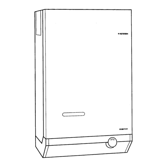
- Page 4 Site Requirements - Page 4 FIG. 2 GENERAL ARRANGEMENT Supplied By www.heating spares.co Tel. 0161 620 6677...
- Page 5 Site Requirements - Page 5 Where the installation of the boiler will be in an unusual 50mm (2 in) at the top (measured from the top of the boiler location, special procedures may be necessary and BS case), except where the optional extra pump cover is to be 6798 gives detailed guidance on this aspect.
- Page 6 REAR OR SIDE FLUEING - Page 6 MAXIMUM LENGTH ‘X’ STANDARD FLUE 510mm SYSTEM (20in) 1 METRE FLUE 955mm SYSTEM (37in) FIG. 4 FLUE LENGTHS ELECTRICITY SUPPLY A 240 volts ~ 50Hz, single phase electricity supply The supply to the boiler and its associated fused to 3 amperes, must be provided in accordance equipment should be controlled by a 3A fused with the latest edition of the I.E.E.
- Page 7 Technical Data - Page 7 INJECTOR GAS RATE INPUT OUTPUT BURNER PRESSURE SIZE m3/h (ft3/h) kW(Btu/h) kW(Btu/h) mbar in wg 4.9mm 3.00(105.9) 32.1(109500) 23.5(80000) 10.0 3.31(117.0) 35.4(121000) 26.4(90000) 12.0 3.62(128.0) 38.8(132500) 29.3(100000) 14.0 CIRCULATION PUMP SELECTION TABLE 2 The resistance through the heat exchanger when operating with a water flow rate producing an 11 C temperature riseat BOILER RESISTANCE...
- Page 8 Technical Data - Page 8 The System temperature in the boiler is high, thus preventing nuisance operation of the overheat thermostat. If a three port diverter The boiler must be used on INDIRECT hot water systems only. It is valve is used as shown in FIG. 6, a by-pass is not necessary suitable for use on open vented gravity domestic hot water/pumped since one circuit is always open.
- Page 9 Technical Data - Page 9 Boiler Heat Exchanger: 6.5 litres Cylinder Small Bore Pipework: 1 litre per kW of The hot water cylinder must be an indirect coil type or a system output direct cylinder fitted with an immersion calorifier suitable for operating at a gauge pressure of 0.3 bar Micro Bore Pipework: 7 litres...
- Page 10 Technical Data - Page 10 Fig 7 Fig 8 Supplied By www.heating spares.co Tel. 0161 620 6677...
- Page 11 INSTALLATION INSTRUCTIONS - Page 11 is the law that all gas appliances are installed and serviced CARTON 2, FLUE SYSTEM PACK:- by Competent persons as stated in Gas Safety (Installation STANDARD OR 1 METRE HORIZONTAL FLUE and Use) Regulations 1994. SYSTEMS For Health and Safety information see back page.
- Page 12 Installation Instructions - Page 12 Fig. 11b REAR FLUE Fig. 11a SIDE FLUE 1. Measure wall thickness (dimension ‘Y’). 1. Measure from outside face of wall to the side of boiler 2. Take air/flue duct assembly and measuring from the casing reference line (dimension ‘x’).
- Page 13 Installation Instructions - Page 13 FIG. 13 SECTIONAL VIEW OF AIR/FLUE DUCT ASSY THROUGH WALL 4. Protect duct where it is likely to come into contact with 5. Insert the assembly into the wall sliding the rope wet mortar by using adhesive tape provide (accessory sealing ring along the air duct into the flue sealing pack E).
- Page 14 Installation Instructions - Page 14 LIFTING THE BOILER Lift the boiler onto its mounting bracket. FIG. 15 FIG. 16 TRANSPORTATION FOOT Position boiler on its mounting bracket so that the sides of Locate the studs on the air duct flange through the boiler the boiler line up with the reference lines ‘C’...
- Page 15 Installation Instructions - Page 15 FIG 20. PIPE CONNECTIONS FIG. 19 LOCATION OF PRESSURE SENSING TUBES Connect system pipework to the boiler, compression fittings are recommended. A drain off tap should be If the boiler is to be used on a gravity DHW system installed close to the boiler if it is in a low point of the refer to Page 16, overheat thermostat positioning system.
- Page 16 This may not be required if a Potterton Electronic Programmer is used as this incorporates a junction box. The principle of wiring is shown in FIG. 22.
- Page 17 Installation Instructions - Page 17 FIG. 24 ROUTING OF ELECTRICAL WIRING Following the pump manufacturer’s instructions connect the pump supply wires to terminals marked PUMP L, N, Gravity Domestic Hot Water/Pumped Central the boiler terminal block. Route the cable through the HeatIng Systems.
- Page 18 COMMISSIONING - Page 18 Open Vented Systems refit the plug into the socket on the left hand side of the control box see FIG. 24. Remove the pump and flush out the system thoroughly with cold water. Refit the pump. Fill and vent the system. Examine for leaks. Refit the combustion chamber front panel.
- Page 19 Commissioning - Page 19 FIG. 26 MAIN BURNER PRESSURES ADJUSTMENT With the burner set to its correct pressure, the firing rate Gravity Hot Water/Pump Over-Run Thermostat given in TECHNICAL DATA should also be obtained and this should be checked by meter reading at least 10 The function of this thermostat is determined by the minutes after the main burner has been lit.
- Page 20 Commissioning - Page 20 Fig. 27 FUNCTIONAL FLOW DIAGRAM Fig. 28 BOILER WIRING DIAGRAM Supplied By www.heating spares.co Tel. 0161 620 6677...
- Page 21 Servicing is best arranged by a contract placed with Turn off the boiler gas service cock. Potterton Myson Ltd., and further details are available from Service Operations at Warwick. NOTE: After completing any servicing or replacement of...
- Page 22 Servicing Instructions - Page 22 Remove screws securing the combustion chamber front pilot injector does not fall out during this operation. panel and remove panel. Lightly brush the pilot and its shield to remove any Disconnect the fan supply leads from the connector deposits.
- Page 23 Servicing Instructions - Page 23 Refit the burner and gas control valve assembly into the Disconnect the electrical supply from the gas valve. Note: White boiler, ensuring that the locating pin on the rear of burner Rodgers, has individual Wire positions. Refer to engages correctly into the rear support bracket.
- Page 24 Servicing Instructions - Page 24 as follows:- Remove controls cover, case door and combustion chamber front panel as described in A. ‘Preparing the Boiler for white wires from the control thermostat Servicing’, operations A, B and C. brown wire from overheat thermostat Disconnect the electrode lead from electrode.
- Page 25 Servicing Instructions - Page 25 GRAVITY DHW/PUMPED CENTRAL HEATING Replacement is the reverse of removal. The bulb of the new thermostat should be coated with heat conducting NOTE: If the boiler is fitted with a right hand flue, remove flue paste.
- Page 26 Servicing Instructions - Page 26 Fig. 31 FAULT FINDING CHART Supplied By www.heating spares.co Tel. 0161 620 6677...
- Page 27 SHORT PARTS LIST - Page 27 KEY No. P.I.L. G.C. Part No. Part No. Pilot and Electrode Assembly including items 2-4 212806 337 857 Pilot Injector 402915 381 656 402945 337 858 Olive 402944 337 859 Electrode 402925 382 448 Electrode Lead 407698 337 863...
- Page 28 HEALTH AND SAFETY INFORMATION FOR THE INSTALLER AND SERVICE ENGINEER - Page 28 Under the Consumer Protection Act 1987 and section 6 of the Health and Safety at Work Act 1974, we are required to provide information on substances hazardous to health. Small quantities of adhesives and sealants used in the product are cured and present no known hazards.
Need help?
Do you have a question about the Profile and is the answer not in the manual?
Questions and answers