
Related Manuals for Potterton Promax System HE


Summary of Contents for Potterton Promax System HE
- Page 1 Promax System HE Wall Mounted Powered Flue Condensing Boiler Gas Fired Central Heating Unit Installation and Servicing Instructions Please leave these instructions with the user...
- Page 2 41 590 69 Guarantee The boiler meets the requirements of Statutory Instrument “ The Boiler (Efficiency) Regulations Your Potterton Promax System HE is 1993 N 3083” and is deemed to meet the designed and produced to meet all the requirements of Directive 92/42/EEC on the energy relevant Standards.
-
Page 3: Table Of Contents
Contents Section Page Introduction General Layout Appliance Operation Technical Data Dimensions and Fixings System Details Site Requirements Installation Electrical 10.0 Commissioning the Boiler 11.0 Fitting the Outer Case 12.0 Servicing the Boiler 13.0 Changing Components 14.0 Fault Finding 15.0 Short Parts List... -
Page 4: Introduction
“Benchmark” Log Book Flue Extension 0.25M 241692 Flue Extension 0.5M 241694 As part of the industry-wide “Benchmark” initiative all Potterton boilers now Flue Extension 1M 241695 (Use two kits for 2M etc.) include an Installation, Commissioning and Service Record Log Book. -
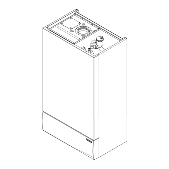
Page 5: General Layout
2.0 General Layout Layout (Figs. 3,4 & 5) Wall Plate Flue Elbow Heat Exchanger Burner Air Box Fig. 6 Fan Protection Thermostat Fan Assembly Condensate Trap Fig. 5 13/14 Gas Tap Gas / Air Ratio Valve Electronics Housing Transformer Flow Temperature Safety Thermostat - Black Flow Temperature Thermistor - Red Flow Switch (dry fire protection) Circulation Pump... -
Page 6: Appliance Operation
3.0 Appliance Operation Mains On. 1. Switched Live On: When the switched live switches on pump overrun occurs. Pump Overrun Pump Overrun 2. Pump Overrun: The pump is on while the fan, for 1 minute ? spark generator and gas valve are off. If at any stage during pump overrun the flow temperature is less than the set point and the flow switch is made then fan purge occurs. -
Page 7: Technical Data
Dimensions Projection 150mm SEDBUK Declaration For Potterton Promax System HE The seasonal efficiency (SEDBUK) is 90.9 % Central Heating Circuit available Pump Head This value is used in the UK Government’s Standard Assessment Procedure (SAP) for energy rating of dwellings. -
Page 8: Dimensions And Fixings
5.0 Dimensions and Fixings DIMENSIONS A 850mm 3° (1 in 20) B 325mm C 490mm D 125mm Ø Min. E 150mm F 125mm 360° Orientation The 3° (1 in 20) fall provided by the elbow is to allow condensate to run back to the boiler, for disposal through the condensate Tube Ø... -
Page 9: System Details
• It is important to check the inhibitor concentration after installation, system modification and at every service in accordance with the manufacturer’s instructions. (Test kits are available from inhibitor stockists.) • For information or advice regarding any of the above contact the Potterton Helpline. - Page 10 & TRV’s only does not produce the best results. Thermal Stores 1. When the Potterton Promax System HE is fitted in conjunction with a thermal store, jumper 2 must be removed from the Control PCB, see Fig. 32a...
- Page 11 6.0 System Details System Filling and Pressurising 1. A filling point connection on the central heating return pipework must be provided to facilitate Double initial filling and pressurising and also any Check subsequent water loss replacement/refilling. Valve 2. The filling method adopted must be in Stop Valve accordance with all relevant water supply bye- laws and use approved equipment.
-
Page 12: Site Requirements
WARNING - The addition of anything that may interfere with the normal operation of the appliance 200mm without the express written permission of Potterton could invalidate the appliance warranty and infringe the G (Installation and Use) R Fig. - Page 13 7.0 Site Requirements Ventilation of Compartments 1. Where the boiler is installed in a cupboard or compartment, no air vents are required for cooling purposes providing that the minimum dimensions below are maintained. Sides 25mm 200mm Bottom 200mm Front 100mm 2.
- Page 14 7.0 Site Requirements Flue NOTE: Due to the nature of the boiler a plume of water vapour will be discharged from the flue. This should be taken into account when siting the flue terminal. 1. The following guidelines indicate the general requirements for siting balanced flue terminals.
- Page 15 Fig. 18a centrally over the terminal and fixed as illustrated. Pictorial examples of flue runs where EQUIVALENT flue length equals 4m 7.12 Vertical Flue 1. Only a flue approved with the Potterton Promax System HE can be used. Fig. 19...
- Page 16 Standard Flue 7.0 Site Requirement 7.13 Flue options Concentric The maximum equivalent lengths are 4m (horizontal) or (vertical). There lengths exclude the standard elbow and flue/terminal assembly (horizontal) and terminal assembly (vertical). Twin Flue The total maximum equivalent flue length is 150m. NOTE: Each 1m of flue duct should be calculated as 2m.
-
Page 17: Installation
The gas supply, gas type and pressure must be checked for suitability before connection (see Section 7.6). NOTE: If the boiler is to be pre-plumbed, PROMAX SYSTEM HE follow both these instructions and those on BOILER the boiler pack. 1. Remove the fixing template (Fig. 20) from the fixing carton. - Page 18 Preparing The Boiler 1. Remove the outer carton. 2. Remove the internal packaging. 3. Lift the outercase upwards and remove (Fig. 23). Potterton declare that no substances harmful to health are contained in the appliance or used during appliance manufacture. Fig. 23...
- Page 19 8.0 Installation Top Hooks Fitting The Boiler (Fig. 24) 1. Remove the tape from the tap rail on the support bracket and fit the central heating return filter (Fig. 25). 2. Lift the boiler using the lower edges of the combustion box.
- Page 20 8.0 Installation Wall Thickness Fitting The Flue Before fitting the flue, check the condensate drain integrity (see section 8.5). 3° (1 in 20) IMPORTANT: The flue should always be installed with a 3° (1 in 20) fall from terminal to elbow, to allow condensate to run back to the boiler.
- Page 21 (Fig. 30). If necessary fit a terminal guard (see section 7.11). Gasket VERTICAL FLUEING 1. Only a flue approved with the Potterton Promax System HE Boiler can be used. Fig. 30 Flue Trim Fig. 29...
- Page 22 8.0 Installation Making The Electrical Connections WARNING: This appliance must be earthed 1. The electrical connections are on the left hand side of the unit behind the facia inside the electrical box. 2. Undo the two screws securing the electrical box cover and remove the cover (Fig.
-
Page 23: Electrical
9.0 Electrical Schematic Wiring Diagram Control bk bk b bk o o o o o o o o Ignition Dry Fire Flow Switch User PCB Detection Electrode Transformer Valve Thermistor Casing Condensate Stat Trap Earth Electrode Spark Electrode Pump Overheat Stat N P/F Mains... - Page 24 9.0 Electrical Illustrated Wiring Diagram Flow Switch Interface Sensing Electrode Flow Temperature Thermistor Control w b y r v g o bk Condensate Trap Fan Protection Thermostat Connector with blue label Ignition Safety Thermostat Valve Transformer Earth Mains Spark and Input Earth Electrode Wiring Key...
-
Page 25: Commissioning The Boiler
10.0 Commissioning the Boiler 10.1 Commissioning the Boiler 1. Reference should be made to BS 5449 Section 5 when commissioning the boiler. 2. Flush the whole system using a suitable flushing agent (see Section 6.2) and vent the radiators. Check for water leaks. 3. -
Page 26: Fitting The Outer Case
11.0 Fitting the Outer Case 11.1 Fitting The Outer Case 1. Position the outercase on the chassis, ensuring that the four slots in the side flanges align with the hooks on the chassis (Fig. 36). 2. Insert the two fixing screws into the sides of the chassis (Fig. -
Page 27: Servicing The Boiler
PCB remains live. Therefore it is important to isolate the electrical supply. Hazardous materials are not used in the construction of Potterton products, however reasonable care during service is recommended. When replacing the combustion box door after servicing it is essential that the retaining screws are tightened fully. - Page 28 12.0 Servicing the Boiler 12.1 Annual Servicing (Cont) 11. To clean the heat exchanger and burner proceed as follows: a) Disconnect the electrical leads to the fan component protection sensor (Fig. 41). b) Loosen the screw retaining the gas injector pipe at the venturi (Fig.
-
Page 29: Changing Components
Heat Exchanger important to isolate the electrical supply. Manifold Hazardous materials are not used in the construction of Potterton products, however reasonable care during service is recommended. When replacing the combustion box door after changing components it is essential that the retaining screws are tightened fully. - Page 30 13.0 Changing Components Flowswitch 13.3 Flowswitch (Fig. 46) Flow Pipe 1. Drain the boiler (see Section 13.1 paragraph 2 & 3). 2. It may be necessary to remove the expansion vessel (see Section 13.5). 3. Remove the clip securing the flow pipe to the flowswitch.
- Page 31 13.0 Changing Components The Pump, interface PCB, pressure gauge and pressure relief valve can be accessed after hinging down the facia box. 1. Release the facia securing screws ( turn) and hinge down the facia box. 13.7 Pump (Fig. 49) Facia Box 1.
- Page 32 13.0 Changing Components 13.10 Interface PCB Interface PCB Electrical Connections 1. Pull the control knob off the spindle and remove the securing nut and washer (Fig. 53). 2. Lift the PCB from the facia box and remove the electrical connections (Fig. 54). 3.
- Page 33 13.0 Changing Components The control and ignition boards can be accessed on the removal of the main Electrical Box Cover electrical box cover. 1. Remove the two screws securing the main electrical box cover (Fig. 59). 13.13 Control Board (Fig. 60) 1.
- Page 34 13.0 Changing Components The fan and venturi, gas valve, injector pipe, condensate trap, fan protection sensor, spark and sensing electrodes can be accessed and changed on the removal of the airbox door panel. 1. Remove the airbox door panel by loosening the four turn screws (Fig.
- Page 35 13.0 Changing Components The removal of the fan is necessary to enable the changing of the injector pipe, condensate trap and gas valve (see section 13.17). 13.18 Injector Pipe (Fig. 66) 1. Remove the injector pipe by pulling out from the ‘O’...
- Page 36 13.0 Changing Components Combustion Box Door Panel The burner and heat exchanger can be changed after removal of the combustion box door. To change the heat exchanger, the fan and burner must be removed first (see section 13.17 & 13.21). 1.
- Page 37 13.0 Changing Components 13.23 Heat Exchanger Lower Insulation (Fig. 73) 1. Remove all components in the base of the airbox. 2. Remove the burner (see section 13.21). 3. Remove the four bolts securing the combustion box base. 4. Remove the combustion box base. 5.
-
Page 38: Fault Finding
14.0 Fault Finding Go to Mains LED HIGH MAINS LED OFF off ? section of the fault finding instructions. Mains On Boiler On (Green) (Yellow) Go to Overheat or Control Mains LED Lockout (Red) MAINS LED FLASHING Knob flashing ? section of the fault finding instructions. - Page 39 Mains LED Off 14.0 Fault Finding boiler supply Replace with 3A fuse. fuse OK ? Is there 230 V at mains No mains supply to input terminal boiler. block (A) ? there 230 V at Wiring from mains input mains input connection terminal block to control to control PCB PCB faulty.
- Page 40 14.0 Fault Finding Mains LED Flashing control knob Switch on on ? wiring from control Rectify wiring. PCB to interface PCB OK (F) ? Does boiler Replace control PCB. produce heat ? Replace interface PCB. Control bk bk b bk o o o o o o o o Ignition Dry Fire...
- Page 41 14.0 Fault Finding Dry-fire Lockout Is there Fill system and water in system switch pump on. and boiler on ? wiring to pump pump running ? Rectify wiring. OK (R) ? Replace pump. flow switch short Replace control PCB. circuit (G) ? flow switch Replace flow switch.
- Page 42 14.0 Fault Finding Safety Lockout Thermistor Open Circuit Open circuit across Replace thermistor thermistor When connections ? flow temp < 60°C. Replace safety Safety thermostat open circuit ? (measured at thermostat (black) safety thermostat) Open circuit Wiring from across thermistor thermistor to logic connections on PCB faulty...
- Page 43 14.0 Fault Finding No Fan No Lockout Reset flow temperature Replace flow thermistor between 0.5k Flow overheat temperature and 20k ? (measured at thermostat will not flow temperature flow temperature thermistor (red) thermistor) reset until flow > 60° C ? temperature <...
- Page 44 The polarity of the 14.0 Fault Finding 230V S/L-N & L-E mains input to the at mains input boiler is reversed. This terminal block ? Ignition Lockout must be rectified. Is there at least 18.1 mbar Incorrect gas dynamic at gas supply to boiler.
- Page 45 14.0 Fault Finding Control bk bk b bk o o o o o o o o Ignition Dry Fire Flow Switch User PCB Detection Electrode Transformer Valve Thermistor Casing Condensate Stat Trap Earth Electrode Spark Electrode Pump Overheat Stat N P/F Mains Optional Input...
-
Page 46: Short Parts List
15.0 Short Parts List Short Parts List G.C. Description Manufacturers Part No. E06 058 Flow Temperature Thermistor (Red) 240670 E06 059 Flow Switch 242459 E06 060 Safety Thermostat (Black) 242235 E06 064 Control PCB E06 065 Ignition PCB 241838 E06 066 Transformer 240236 E06 074... - Page 47 Potterton manufacture a comprehensive range of products for the domestic heating market. Gas Central Heating Boilers (Wall, Floor and Fireside models). Independent Gas Fires. Renewal Firefronts. Gas Wall Heaters. Solid Fuel Fires. If you require information on any of these products, please write, telephone or fax to the Sales Department.
- Page 48 Potterton, Baxi UK Limited, Brownedge Road, Bamber Bridge, Preston, Lancashire. PR5 6SN After Sales Service 08706 096 096 Technical Enquiries 08706 049 049 www.baxi.com Comp N 5106703 - Iss E - 2/02...
Need help?
Do you have a question about the Promax System HE and is the answer not in the manual?
Questions and answers