Table of Contents

Related Manuals for Potterton Promax Store 24


Summary of Contents for Potterton Promax Store 24
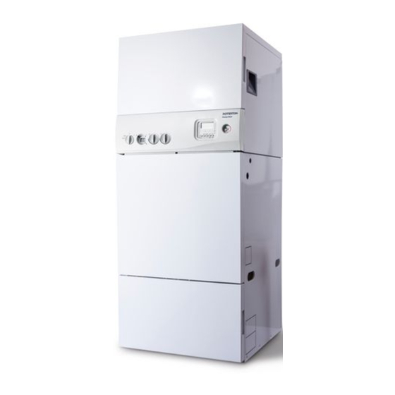
- Page 1 United Kingdom Installation and Service Manual Condensing Boiler with Integrated Hot Water Storage P P romax Store These instructions include the Benchmark Commissioning Checklist and should be left with the user for safe keeping.
- Page 2 Natural Gas Building Regulations and the Benchmark Commissioning Checklist Potterton Promax 24 Store ErP Building Regulations (England & Wales) require notification G.C.N 41 592 47 (90 litre) of the installation of a heating appliance to the relevant G.C.N 41 592 48 (115 litre) Local Authority Building Control Department.
-
Page 3: Installer Notification Guidelines
Installer Notification Guidelines Choose Building Regulations Notification Route Competent Person's Building Control Self Certification Scheme Install and Commission this Contact your relevant Local appliance to manufacturer's Authority Building Control instructions (LABC) who will arrange an inspection or contact a government approved inspector Complete the Benchmark Checklist... -
Page 4: Table Of Contents
Storage, Unpacking and Handling Gas Supply Benchmark Commissioning Checklist Electricity Supply Potterton is a member of the Benchmark initiative and Location of Boiler fully supports the aims of the programme. Benchmark Compartment Installation & Ventilation has been introduced to improve the standards of... - Page 5 Panel Removal Important: Refer to Page 11 for Storage, Unpacking and Handling Instructions. Top & Bottom Section Top Section Lift Heat Engine onto Rollers Cylinder. Ensure the rollers engage into location channels. Tilt and slide until front location pegs drop into position on the cylinder.
- Page 6 Technical Data Unless indicated, data shown relevant to all models 90 litre 115 litre 150 litre Classifications Appliance category CAT I 2 H Flue Type C 13 - C 33 - C 53 (as supplied) NOx Class Cylinder Insulation CFC, HCFC = 0% Input Qn Hs (hot water/central heating) - gross 7.8 - 27.4 kW Output to CH Pn (non-condensing)
-
Page 7: Technical Parameters
Technical Parameters Technical parameters for boiler combination heaters Potterton Promax 24 Store ErP Condensing boiler Low-temperature boiler B1 boiler Cogeneration space heater Combination heater Prated Rated heat output Useful heat output at rated heat output 24.0 24.0 24.0 and high temperature regime... - Page 8 Note: Note: Cupboard At these minimum clearances above Removable Top Panel intended the appliance, adequate working to provide access MUST be provided. access. 650 max Removable Top Panel Door Frame 400 mm 400 mm Recommended Recommended Typical Bulkhead Installation Typical Cupboard Installation with rearwards horizontal concentric flue with twin vertical air/flue pipes Fig.
- Page 9 Introduction Checklist of supplied components: Operation Cold water control pack including: The boiler control works on the principle of “hot water Expansion Vessel priority” so the central heating output may be Expansion Vessel Bracket temporarily delayed if the hot water temperature Expansion Vessel Braided Hose with Seals drops below the selected temperature e.g.
-
Page 10: Codes Of Practice
Codes of Practice In GB the following Codes of Practice apply: Standard Scope The appliance is suitable only for installation in GB and BS6891 Specification for low pressure gas pipework IE and should be installed in accordance with the rules in in domestic premises. -
Page 11: Installation Requirements
1. Installation Requirements Storage, Unpacking & Handling from any other appliances in the house and must be governed at the meter. This boiler is delivered in two sections for safety and The gas installation should be in accordance with the ease of handling. -
Page 12: Compartment Installation & Ventilation
I.S. 813 "Domestic Gas Installations" and the current ETCI rules. This is a “room sealed” condensing boiler. Flue systems are supplied in kits, or components can be ordered individually from Potterton. Only Promax Store 1.4 Compartment Installation and flue components (which are designed for condensing Ventilation operation) can be used. - Page 13 General Requirements for Horizontal Flue aluminium shield at least 750 mm long must be fitted Terminations to the underside of the plastic or painted surface. Detailed recommendations for flueing are given in g) Where installation will be in an unusual location, BS5440: Part 1.
- Page 14 Plume Displacement Kit IMPORTANT: If fitting a Plume Displacement Flue Kit, the air inlet must be a minimum of 100mm from any opening windows or doors Air Inlet Opening Window or Door 150mm MIN. Likely flue positions requiring a flue terminal guard Terminal Position with Minimum Distance (mm) For IE, refer to I.S.
- Page 15 Flue Options 1. The Promax 24 Store can be fitted with flue systems as illustrated. 2. Maximum permissible equivalent flue lengths are:- 10 metres (60/100 system - vertical & horizontal) 20 metres (80/125 system - vertical & horizontal) 15 metres (80/80 twin pipe) 3.
- Page 16 Flue Deflector (Fig. 5b) 1. If required a flue deflector is available from your Potterton stockist. 2. Push the flue deflector over the terminal end. It may point upwards as shown, or up to 45° either way from vertical.
-
Page 17: Water Supply & Systems
1.6 Water Supply be effective in reducing limescale but require correct siting and regular replenishment to remain operational. They should generally not be fitted where heat could Mains Supply Requirements impair their performance. Other types of device can It is essential that the mains supply pressure and inhibit scale formation but their effectiveness may vary. -
Page 18: Discharge Pipework
Building play or otherwise come into contact with Control Officer or Potterton. discharges a wire cage or similar guard is positioned to prevent contact, whilst maintaining G3 Requirement “...there shall be precautions ... - Page 19 Temperature relief valve to tundish Warnings • Under No circumstances should the factory Tundish fitted Temperature/Pressure Relief Valve be removed other than by Authorised Potterton 600mm maximum personnel. To do so will invalidate any Discharge below fixed grating warranty or claim.
-
Page 20: Installation
2. Installation 2.1 Install the boiler 5. Remove the DHW temperature sensor from the boiler fitting kit and uncoil it. 6. Drop down the boiler facia panel. Identify the electrical Before starting an installation, check that the correct flue connection end of the DHW temperature sensor ("A% in kit and correct capacity cylinder have been supplied. - Page 21 Tundish Domestic Hot Water Sensor Isolating Valve Plumbing Pressure Gauge 'NO GO' Area Immersion Filling Loop Heater Potterton Promax Store Pipework shown as this 150 litre model shown NOT SUPPLIED D.H.W. CH Flow Outlet Gas Inlet Discharge Pipe CH Return Mains Cold Inlet Fig.
- Page 22 2.4 Condensate Drain Pipe Before fitting, fill the condensate trap with water. Fit the steady bracket (with round hole) for the condensate trap to the lower pair of holes in the left hand cylinder side panel. Snap the C-shaped bracket into the groove in the condensate connector.
- Page 23 Ø240mm Wall Bolts & Plugs Secondary Threaded Washer Expansion Vessel 300mm Expansion Vessel Support Bracket Nut & Balanced 22mm 15mm Washer Cold Feed Expansion Vessel Support Strap To Shower Stop Valve Mains Cold Inlet 22mm 22mm and cold feed to kitchen Combination tap.
-
Page 24: Connect The Power Supply Cable
2.5 Connect the Water System Read and observe recommendations in Section 1.6 and see Fig. 11. Secure the combination reducing valve - a wall Graph of Central Heating Head vs. Flow bracket is provided in the accessory pack. 22mm copper tube is recommended for both the inlet and outlet connections. - Page 25 Making The Electrical Connections To connect the mains input cable proceed as follows:- 1. Remove all the outer panels. Always fit fast 2. Completely undo the screws securing the blow 2A fuse Fused supply 3A facia panel and hinge it down. 230V ~ 50Hz Live (brown) 3.
- Page 26 2.7 Immersion Heater The immersion heater is rated 3kW at 240V and must be wired to a separate, suitably rated electrical supply. THERE MUST BE NO INTERCONNECTION WITH THE WIRING TO THE BOILER. WARNING: THE IMMERSION HEATER MUST BE EARTHED. Promax Store It should be installed in accordance with the current IEE Wiring Regulations and be wired through a double pole isolating...
- Page 27 2.7.3 Maintenance Requirements Unvented hot water systems have a continuing maintenance requirement in order to ensure safe working and optimum performance. It is essential that the relief valve(s) are periodically inspected and manually opened to ensure no blockage has occurred in the valves or discharge pipework. Similarly cleaning of the strainer element and replacement of the air in the expansion vessel will help to prevent possible operational faults.
-
Page 28: How To Drain Hot Water Storage Cylinder
How to Drain Hot Water Storage Cylinder Isolate mains water supply at stop valve on Inlet Control Group and close -turn valve (handle at 90° to valve body) on double check valve - see Fig. 14. Fit a hosepipe to the tail of the drain valve (secure with “Jubilee” clip), and run open end to a low level where water can be safely drained. -
Page 29: Commissioning
When checking for gas soundness open only be carried out by a suitably qualified all windows and doors in the room. person. Potterton offer this service Extinguish all naked lights, cigarettes, pipes, etc. on a chargeable basis. © Baxi Heating UK Ltd 2015... -
Page 30: Commission The Boiler
3.1 Commission the Boiler Sealed Primary System Automatic Air Vent: This is built into the pump. Leave 1. Ensure that gas supply is turned OFF at the gas the cap open during and after commissioning. cock. Manual Air Vent: This must be used to remove as much 2. - Page 31 Commissioning the Boiler - Combustion Check 1. Reference should be made to BS:EN 12828 & 14336 when commissioning the boiler. 2. At the time of commissioning, complete all relevant sections of the Benchmark Checklist at the rear of this publications. 3.
- Page 32 Set Boiler to Maximum Rate Allow the combustion to stabilise. Do not insert probe to Checking Combustion avoid "flooding% the analyser. 1. Follow the flow chart opposite. Perform Flue Integrity Combustion Check Insert the analyser probe into the air inlet test point, allowing the reading to stabilise.
-
Page 33: Hand Over To The User
Check the Operational (Working) Gas Inlet Pressure 4. With flow to the CH circuit, bleed every radiator and the pipework high points until all air or air/water mix 1. The gas valve is factory set and the burner pressure has been removed. changes as the fan modulates when demand on the boiler alters. -
Page 34: Service & Replacement Of Parts
4. Service & Replacement of Parts To ensure safe, efficient operation of the boiler, it is 6. Turn off the mains water supply at the Inlet Control necessary to carry out routine servicing at regular Group and release system pressure by opening a intervals. -
Page 35: General Access
4.1 General Access WARNING: Before attempting to remove any component from the boiler first disconnect the mains electricity supply by removing the plug from the wall General Access socket or by switching off the boiler at the external isolating switch. Pull forward Front Panel at the bottom and lift off IMPORTANT: After removal or replacement of any... -
Page 36: Automatic Air Vent
4.3 Expansion Vessel, Pump & Pressure Switch Re-assemble all parts in reverse order. 1. Check that the cap on the auto air vent is open. Turn the 3 isolating valves OFF and Expansion Vessel locally drain the boilers% circuit by opening the primary pressure relief valve. -
Page 37: Pressure Sensor/Pressure Relief Valve
4.4 Pressure Sensor/PRV Re-assemble all parts in reverse order. 1. Perform 4.1 General Access. Isolating Valve 2. Isolate three valves as shown and open the cap on the auto air vent. 3. Release pressure by opening the pressure relief valve. Gas Cock 4. -
Page 38: Gas Valve
Gas Valve Venturi Inlet 1. Turn the gas cock OFF and disconnect Pipe the electrical plug. Sealing Washer 2. Pull off the earth lead and sensing pipe. Sensing 3. Undo the nuts on the venturi inlet pipe Pipe and valve inlet pipe. Remove the gas valve. Gas Valve 4. -
Page 39: Igniter
Igniter Bracket 1. Remove the air box front cover. 2. Disconnect the igniter feed plug and the Igniter electrode leads, noting their positions. 3. Undo the screw securing the bracket to the boiler. Igniter Feed Plug 4. Remove the igniter and transfer the bracket to the new component. -
Page 40: Burner
4.10 Burner 1. Remove the fan/manifold assembly - see Section 4.6. 2. Undo the screws securing the spacer to the cover. Cover 3. Withdraw the burner from the cover and replace with the new one. Gasket 4. Replace the burner gasket. Extension Piece 5. -
Page 41: Diverter Valve Actuator
4.12 Diverter Valve Actuator Re-assemble all parts in reverse order. 1. Perform 4.1 General Access. 2. Disconnect the electrical connector at the actuator. 3. Release the locking catch and twist the actuator until it unlocks from the valve and remove from the boiler. Diverter Valve Complete Re-assemble all parts in reverse order. -
Page 42: Heat Exchanger
4.14 Heat Exchanger NOTE: Replacing the heat exchanger involves disconnecting the appliance from the flue and air pipes. It is essential that the flue system is fully reinstated and tested so we recommend that the appropriate replacement flue pipe and fittings be obtained before starting this work. - Page 43 4.15 Replacement of Immersion Heater and Immersion Heater Combined Thermostat/Thermal Cut-out The cylinder must be fully drained prior to removing the immersion heater. Refer to Section 2.8 for the procedure to drain the unit. Important: Ensure ALL power supplies are isolated before starting work on the boiler. Perform the actions detailed in section 4.1 General Access.
-
Page 44: Gas/Air Valve Setup Procedure
4.16 Gas/Air Valve Setup Procedure Flue Adaptor Checking the CO Test Point 1. The combustion (CO ) may be checked at maximum rate using a suitably calibrated analyser after running the boiler for several minutes. 2. To do this it is necessary to set the boiler to "Calibration Mode%. -
Page 45: Wiring Diagrams
5. Wiring Diagrams Wiring/Functional Flow Diagram Fig. 27 © Baxi Heating UK Ltd 2015... - Page 46 Flow Thermistor Cylinder Overheat Stat Thermistor Water Pressure Flue Thermistor Switch Flame Sensing X400 Timer X401 Electrode 9 8 7 8 7 6 5 4 3 2 1 Control PCB X501 Pump 6 Way Connector b br Pump Diverter Valve Spark Generator Mains Input...
-
Page 47: Fault Finding
6. Fault Finding Guide Boiler Fault Finding Initial Fault Finding Checks 1. Check that gas, water and electrical supplies are available at the boiler. 2. Electrical supply = 230V ~ 50 Hz. 3. CH water system pressurised to 0.5 bar minimum when the boiler is cold. - Page 48 Refer to Section “Illustrated Wiring Diagram” for position of terminals and components Central Heating - Follow operational sequence Turn selector switch to Go to section "A% The display illuminates Error 110 flashing If the error 110 is still Turn the selector switch to Error 130 flashing flashing.
- Page 49 Domestic Hot Water - Follow operational sequence Turn selector switch to Select HW "On All Day% or Go to section "A% The display illuminates 24Hr at programmer Error 110 flashing If the error 110 is still Turn the selector switch to Error 133 flashing flashing.
- Page 50 Fault Finding Solutions Sections Is there 230V at: Main terminals L and N Check electrical supply Main terminal fuse Replace fuse Display Replace PCB illuminated Check wiring PCB - X1 connector terminals 1,2 Is there 230V at: X3 Connection Pump PCB Check incoming wiring X2 Connection Pump PCB Replace Pump PCB...
- Page 51 Temperature sensors faulty. Cold resistance approximately 10k @ 25° C (DHW and CH sensors) Replace sensor 20k @ 25° C (Flue sensor) (resistance reduces with increase in temp.) Check and correct the connection of the tube between the venturi and gas valve Gas at burner Ensure gas is on and purged...
- Page 52 Check the gas supply pressure: For Natural Gas greater than 10 - 11 mbar Check and correct if necessary 1. The mechanical set of the gas valve (CO2 values - see instruction) 2. Flame sensing electrode and lead connections 3. Flame sensing electrode position Replace PCB Flame current should be more than 0.5 A Replace flame sensing electrode...
- Page 53 7. Short List Of Spare Parts Short Parts List G.C. Description Manufacturers Part No. 5129230 Igniter Electrode 5114702 Sensing Electrode 5117275 Gas Valve 720301001 Burner 5114697 Water Pressure Switch 5114748 Pump 7220533 Flue Thermostat 5114747 NTC Sensor 5114725 Overheat Thermostat 5106291 Pressure Gauge 248090...
-
Page 54: Gas Boiler System Commissioning Checklist
GAS BOILER SYSTEM COMMISSIONING CHECKLIST This Commissioning Checklist is to be completed in full by the competent person who commissioned the boiler as a means of demonstrating compliance with the appropriate Building Regulations and then handed to the customer to keep for future reference. Failure to install and commission according to the manufacturer’s instructions and complete this Benchmark Commissioning Checklist will invalidate the warranty. -
Page 55: Service Record
SERVICE RECORD It is recommended that your heating system is serviced regularly and that the appropriate Service Interval Record is completed. Service Provider Before completing the appropriate Service Record below, please ensure you have carried out the service as described in the manufacturer’s instructions. SERVICE 01 SERVICE 02 Date:... - Page 56 Baxi Customer Support 0344 871 1525 Opening hours Monday - Friday, 8.00am-6.00pm Weekends and Bank Holidays, 8.30am-2.00pm Please note calls may be recorded for training and monitoring purposes baxi.co.uk Register now to activate your warranty: www.baxi.co.uk/registration For the warranty to be maintained, please make sure... Benchmark checklist is completed Warranty is registered with Baxi The boiler has an annual service...
Need help?
Do you have a question about the Promax Store 24 and is the answer not in the manual?
Questions and answers