Table of Contents
Advertisement
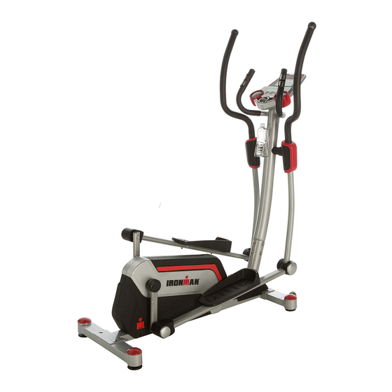
OWNER'S MANUAL
H-Class 610
Smart Technology Elliptical Trainer with Bluetooth
Model 6336
The specifications of this product may vary from this photo and are subject to change without notice.
IRONMAN, IRONMAN TRIATHLON and M-DOT are registered trademarks of World Triathlon Corporation.
This product is licensed by the World Triathlon Corporation.
1
Advertisement
Table of Contents

Related Manuals for Ironman Fitness H-Class 610


Summary of Contents for Ironman Fitness H-Class 610
- Page 1 OWNER’S MANUAL H-Class 610 Smart Technology Elliptical Trainer with Bluetooth Model 6336 The specifications of this product may vary from this photo and are subject to change without notice. IRONMAN, IRONMAN TRIATHLON and M-DOT are registered trademarks of World Triathlon Corporation.
- Page 2 6336.1-082514...
-
Page 3: Table Of Contents
TABLE OF CONTENTS SERVICE ------------------------------------------------------------------------ 4 LABEL PLACEMENT --------------------------------------------------------- 5 PRODUCT SAFETY ---------------------------------------------------------- 6 OVERVIEW DRAWING ------------------------------------------------------ 7 PARTS LIST --------------------------------------------------------------------- 9 HARDWARE LIST & TOOLS ----------------------------------------------- 11 ASSEMBLY ---------------------------------------------------------------------- 12 COMPUTER --------------------------------------------------------------------- 24 TROUBLE SHOOTING & MAINTENANCE ----------------------------- 32 WARM UP ---------------------------------------------------------------------- 33 WARRANTY -------------------------------------------------------------------- 34 FAX FORM ---------------------------------------------------------------------- 35... -
Page 4: Service
SERVICE IMPORTANT: FOR NORTH AMERICA ONLY To request product service and order replacement parts, please call our customer service department at: 1-844-641-7922 Monday through Friday, 8:00 AM-5:00 PM Pacific Standard Time, service@paradigmhw.com or email us at: Please visit our website at www.paradigmhw.com. Please have the following information ready when requesting for service: Your name Phone number... -
Page 5: Label Placement
LABEL PLACEMENT Maximum weight capacity is 275 lbs. AVERTISSEMENT Le poids maximum pout ce produit est 125 kgs. -
Page 6: Product Safety
PRODUCT SAFETY Basic precautions should always be followed, including the following Important safety instructions when using this equipment. Read all instructions before using this equipment. Read all the instructions in this manual and do warm up exercises before using this product. Before exercise, in order to avoid injuring your muscles, warm-up exercise for every muscle group is highly recommended. -
Page 7: Overview Drawing
OVERVIEW DRAWING... - Page 8 OVERVIEW DRAWING...
-
Page 9: Parts List
PARTS LIST Description Qty No. Description Front Stabilizer 40x80x2.0T 22R Right Foot Pedal Rear Stabilizer 40x80x2.0T 23A Lower Crank Cover A (Black) Front Post Ø76x2.0T 23B Lower Crank Cover B (Black) Handlebar Ø32 Belt Pulley Ø214 6L Outer Handlebar Left Ø32x1.6T Belt Pulley Ø180 6R Outer Handlebar Right Ø32x1.6T Handrail Foam Grip Ø32x5.0T... - Page 10 PARTS LIST Description Qty No. Description Allen Bolt 54 Bushing Ø17x35 Washer Ø10xØ16x1.5T 55 Power Supply Cable Spacer Ø12xØ17x9T 56 Tension Bracket & Eyebolt Set Ⅱ Inner C Ring Ø12 57 Sensor with Wire L=150mm Wave Washer Ø12xØ17x0.2T 58 U shape plate Bushing Ø12xØ18x11.5 Self Tapping Screw M4.5x15 Conical Washer Ø8.15xØ11x3.5...
-
Page 11: Hardware List & Tools
HARDWARE LIST & TOOLS (#14))Wave Washer (#35) Cap Nut M10 2 PCS (#34) Carriage 4 PCS Bolt 4 PCS (#39) Hexagon Socket (#40) Nylon Locknut (#41) Hexagon Socket Head Bolt 4 PCS Head Bolt 4 PCS 2 PCS (#43) Carriage Bolt (#44) Nylon Locknut (#42) Washer 4 PCS... -
Page 12: Assembly
ASSEMBLY Tool: Multi Hex Tool with Phillips Screwdriver Front Stabilizer Installation. Lift up the main frame (1) towards the front, and then align the Front Stabilizer (2) onto the front curve of the Main Frame (1). Attach two Carriage Bolts (34) and on the other ends of bolts with two Washers (42) and two Cap Nuts (35). - Page 13 ASSEMBLY Hardware: Tool: Multi Hex Tool with (#34) Carriage Bolt Phillips Screwdriver 2 PCS (#35) Cap Nut M10 2 PCS (#42) Washer 2 PCS 2. Rear Stabilizer Installation. Lift up the Main Frame (1) towards the end, and then align the Rear Stabilizer (3) onto the rear curve of the Main Frame (1).
- Page 14 ASSEMBLY Tool: Allen Wrench 5mm MUST TIGHTEN IN SEQUENCE: A,B,C,D,E,F,G,H. Assemble Front Post. Use the Allen Wrench to remove eight Hexagon Socket Head Bolts (32), eight Spring Washers (101), and eight Curve Washers (38) from the Front Post (4). Connect the Computer Wire (12) from the Front Post (4) with the Extension Sensor Wire (15) from the Main Frame (1).
- Page 15 ASSEMBLY 3. Computer Installation Remove the four Bolts (98) from the back of the computer Remove the Wire Plug (106) from Front Post (4) CAREFULLY insert the Computer Wire (12) into the 9-pin socket on the computer and run the Pulse Wire through the top plate and out the side hole on the Front Post (4). CAUTION: To prevent damage, ensure the wires are NOT folded or pinched during installation.
- Page 16 ASSEMBLY 5. Connect Pulse Wire Attach the Wire Plug (106) onto the Hand Pulse Wire (17) Connect the two ends of the Hand Pulse Wire (17) and gently feed the extra wire length into the round hole until the Wire Plug (106) is installed. 6.
- Page 17 ASSEMBLY 7. Assemble Handlebar Arms Hardware: Insert Handlebar Arm Left (7L) into Outer Handlebar Left (6L) Tighten using two Allen Bolt (39) and Locknuts (40) Repeat for the opposite side (#39) Allen Bolt M8, 4 PCS (#40) Locknut 4 PCS Tool: Allen Wrench 5mm 8.
- Page 18 ASSEMBLY 9. Assemble Foot Bars Insert the Left Foot Bar (9L) onto the Left Crank (10) Tighten with a Wave Washer (70), Washer (71) and Allen Bolt (53) Tool: Repeat for the opposite side Allen Wrench 5mm Hardware: (#53) Allen Bolt 2 PCS (#70) Wave Washer 2 PCS...
- Page 19 ASSEMBLY 10. Assemble Handlebar Arms: “R” is for right side and “L” is for left side. A. Place the Left Handlebar Arm (7L) into the U shape from Left Foot Bar (9L). Align the hole then tighten with one Hexagon Socket Head Bolt (41), one Washer (42) and one Nylon Locknut (44) by using the Allen Wrench and Multi Hex Tool with Phillips Screwdriver until firm and secure.
- Page 20 ASSEMBLY 11. Assemble Front and Rear Covers for Front Post and Handlebar Arm Covers A/B. A. Remove two Round Head Self Tapping Screws (59) from the Handrail Arm Covers A/B (100A, 100B) by using the Multi Hex Tool with Phillips Screwdriver. B.
- Page 21 ASSEMBLY 12. Assemble U Shape Bracket Covers. Place the U Shape Bracket Covers A, B(97A, 97B) around the U Shape Brackets (8). Tighten them with two Self Tapping Screws (59). Attach two End Caps (113) onto the U Shape Bracket Covers A, B Tool: Multi Hex Tool with Phillips Screwdriver...
- Page 22 ASSEMBLY 13. Assemble Foot Bar Covers A/B. Place the Foot Bar Covers-A/B (75A, 75B) around the Left/Right Foot Bars (9L, 9R). Tighten them with two Round Head Self Tapping Screws (59) by using the Multi Hex Tool with Phillips Screwdriver until firm and secure. Attach four Plastic End Caps (114) onto the Foot Bar Covers-A/B (75A, 75B).
- Page 23 ASSEMBLY Rear Stabilizer End Cap Adjusting the Front and Rear Stabilizer End Cap Turn the rear stabilizer end caps on the front and rear stabilizer as needed to level the elliptical. This will help provide stability and eliminate squeaking noises.
-
Page 24: Computer
COMPUTER Speaker input BUTTON FUNCTION: ON/OFF FAN Turn the fan on or o˜ QUICK To start or stop workout START STOP UP/DOWN To select training mode or adjust function value RESET In stop mode, press the button to return to main menu. Press and hold for 2 seconds to reboot the computer and reset all values to 0. - Page 25 COMPUTER DISPLAY FUNCTION Function SettingRange Unit DisplayRange TIME 00:00~99:59 ±1;00:00~99:00 Minutes DISTANCE 0.0~99.99 ±1;00:00~99:00 CALORIES 0~9999 ±10;00:00~9990 PULSE 30~230 ±1; 30~230 SPEED 0.0~99.9 0~999 WATT 0~999 ±5; 10~350 OPERATING PROCEDURE 1.POWER ON/OFF – After connecting the power, console will power on with a long beep sound, LCD display all segments and then enter into User Profile set up mode.
- Page 26 COMPUTER 2.USER PROFILE Press UP/DOWN to select User # Press UP/DOWN to turn profile editing on or off If you choose EDIT ON, you can edit your profile values. Use UP/DOWN and ENTER to input profile value of sex, age, height and weight. The console needs your profiles to better calcu- late the workout values 3.WORKOUT SELECTION...
- Page 27 COMPUTER 3.2. Program Mode Press UP or DOWN to select between 12 different workout programs and then press ENTER to set up Target Time . Press START to start workout. Resistance levels can be adjusted during exercise by pressing UP or DOWN. Press STOP to pause the workout reading, and you can press START to continue the workout.
- Page 28 COMPUTER 3.3 User Program User Program allows you to create your own workouts based on resistance level and time intervals. Press UP and DOWN to create the profile, press ENTER to input additional resistance level, then press and hold ENTER for 2 seconds to exit profile setting. Press START to start work out. Standard work out time is 20 minutes.
- Page 29 COMPUTER 100%...
- Page 30 COMPUTER 3.5 WATT Press UP and DOWN to setting WATT and Time target. Press START to start work out. Press STOP to pause the workout reading, and you can press START to continue the workout. Press RESET to return to main page 4.
- Page 31 COMPUTER 5. Bluetooth Mode Enable Bluetooth on your smart device, search for and connect to the console (name is on the back of the console). When your smart device is connected to the console, the Bluetooth symbol will appear on the LCD. Please note: 1.
-
Page 32: Trouble Shooting & Maintenance
TROUBLE SHOOTING PROBLEM: The elliptical wobbles when in use. SOLUTION: Turn the front or rear stabilizer end caps as needed to level the elliptical. PROBLEM: There is no display on the computer console. SOLUTION: Remove the computer console and verify the wires that come from the computer console are properly connected to the wires that come from the front post. -
Page 33: Warm Up
WARM UP Quadriceps Stretch With one hand against a wall for balance, reach behind you and pull your right foot up. Bring your heel as close to your buttocks as possible. Hold for 15 counts and repeat with left foot up. Inner Thigh Stretch Sit with the soles of your feet together with your knees pointing outward. -
Page 34: Warranty
WARRANTY MANUFACTURER’S LIMITED WARRANTY Paradigm Health & Wellness warrants to the original purchaser that this product is free fromdefects in material and workmanship when used for the purpose intended, under the conditions that it has been installed and operated in accordance with Paradigm’s Owner’s Manual. Paradigm’s obligation under this warranty applies to the following: COMPONENT LENGTH OF WARRANTY... -
Page 35: Fax Form
Paradigm Health & Wellness, Inc. PARTS REQUEST FAX FORM Please fax this form to (1-626-810-2166) OR YOU CAN EMAIL CUSTOMER SERVICE REQUESTS TO service@paradigmhw.com NAME: _______________________________________________________ ADDRESS: ____________________________________________________ CITY ______________ STATE ______________ ZIP ___________________ TELEPHONE: (Day) _____________________________________________ (Night) ____________________________________________ (Email Address) ____________________________________ SERIAL#: __________________________________________ MODEL#: __________________________________________ PURCHASE DATE: ______________________________________________...
Need help?
Do you have a question about the H-Class 610 and is the answer not in the manual?
Questions and answers