
Related Manuals for Savoy 56-765-5MP-SN


Summary of Contents for Savoy 56-765-5MP-SN
-
Page 1: Ceiling Fan
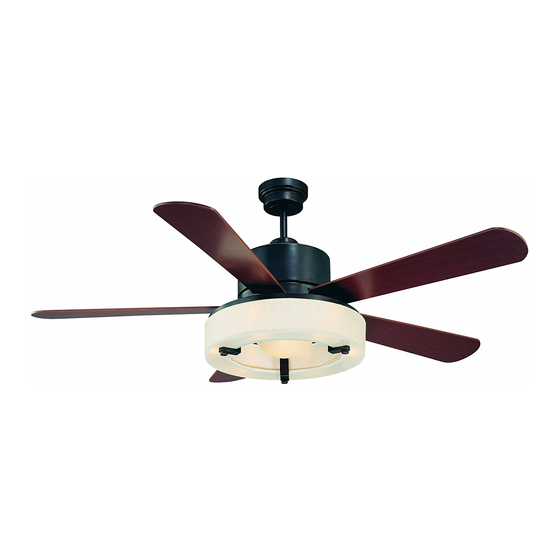
CEILING FAN OWNER'S MANUAL READ AND SAVE THESE INSTRUCTIONS MODEL: 56-765-5MP-SN 56-765-5HK-213 FAN RATING AC 120V. 60Hz CUL LISTED MODEL : AC-552A... -
Page 2: Tools And Materials Required
1. TOOLS AND MATERIALS REQUIRED Philips screw driver Blade screw driver 11 mm wrench Step ladder Wire cutters 2. PACKAGE CONTENTS Unpack your fan and check the contents. You should have the following items; a. Blade set (5) b. Blade support plates (5) c. -
Page 3: Safety Rules
3. SAFETY RULES 1. To reduce the risk of electric shock, insure To avoid personal injury or damage to the electricity has been turned off at the fan and other items, be cautious when circuit breaker or fuse box before working around or cleaning the fan. -
Page 4: Mounting Options
4. MOUNTING OPTIONS If there isn't an existing CUL listed mounting box, then read the following instructions. Disconnect the power by removing fuses or turning off circuit breakers. Outlet box Secure the outlet box directly to the building structure. appropriate fasteners and building materials. -
Page 5: Hanging The Fan
5. HANGING THE FAN Hanger bracket REMEMBER to turn off the power. Follow the steps below to hang your fan properly: Ceiling Step 1. Remove the decorative canopy canopy bottom cover from the canopy by turning the cover counter clockwise. (Fig. 5) Canopy cover Figure 5... -
Page 6: Installation Of Safety Support
6. INSTALLATION OF SAFETY SUPPORT An additional safety support is provided to Hanger bracket Safety cable prevent the fan from falling. Secure the safety cable to the ceiling joist with screw and washer, as illustrated in Figure 9. Figure 9 7. - Page 7 Step 3. (Fig. 12 and 13) Receiver to House Supply Wires Electrical Connections: Outlet box Connect the black (hot) wire from the ceiling to the black wire marked "AC in L" White (neutral) Black (hot) from the receiver. Connect the white Green or bare copper (ground) (neutral) wire from the ceiling to the white...
-
Page 8: Installing The Wall Transmitter
8. INSTALLING THE WALL TRANSMITTER REMEMBER to Shut the Power Off at the Circuit Breaker or Fuse Box. WARNING: HOOK UP IN "SERIES ONLY" DO NOT CONNECT THE HOT AND NEUTRAL WIRES OF ELECTRIC CIRCUIT TO THE TRANSMITTER WALL SWITCH - DAMAGE TO THE SWITCH AND POSSIBLE FIRE COULD OCCUR. -
Page 9: Attaching The Fan Blades
10. ATTACHING THE FAN BLADES Insert the blade through the slot in housing. Align holes in blade and motor and secure with 3 screws and blade support plate. Repeat process with the other blades. (Fig. 16) Slot Blade Blades support Screws plates 11. -
Page 10: Installing The Light Kit
12. INSTALLING THE LIGHT NOTE: Before starting installation, disconnect the power by turning off the circuit breaker or removing the fuse at fuse box. Step 1. Remove the 3 screws from the mounting plate. Step 2. Raise and hold the light kit close to the mounting plate and proceed to do the wire connections. -
Page 11: Lighted Housing Bulb Replacement
14. LIGHTED HOUSING BULB REPLACEMENT 1. Remove the 2 screws from the light kit and take off the lamp cover as shown in Figure 20. Bulbs Screws 2. Replace the defective bulb (10W, 120V AC CANDELABRA base). Lamp cover 3. Place the lamp cover back to the light kit and secure the screws in position. - Page 12 The Reverse switch is located on the top of the motor housing. Slide the switch to the Left for warm weather operation. Slide the switch to the Right for cool weather operation. Speed setting for warm or cool weather depend on factors such as the room size. Ceiling height, number of fans and so on.
-
Page 13: Troubleshooting
16. TROUBLESHOOTING Problem Solution Fan will not start. 1. Check circuit fuses or breakers. 2. Check line wire connections to the fan and switch wire connections in the switch housing. CAUTION: Make sure main power is off. 3. Check to make sure the dip switches from the transmitter and receiver are set to the same frequency.
Need help?
Do you have a question about the 56-765-5MP-SN and is the answer not in the manual?
Questions and answers