Table of Contents
Advertisement
CAUTION, MICROWAVE RADIATION ............................................................................................................ 1
WARNING ..........................................................................................................................................................1
PRODUCT SPECIFICATIONS ......................................................................................................................... 2
GENERAL INFORMATION ............................................................................................................................... 2
APPEARANCE VIEW ....................................................................................................................................... 3
OPERATION SEQUENCE ............................................................................................................................... 4
FUNCTION OF IMPORTANT COMPONENTS ................................................................................................ 5
SERVICING ...................................................................................................................................................... 6
TEST PROCEDURE ........................................................................................................................................ 8
TOUCH CONTROL PANEL ............................................................................................................................ 14
COMPONENT REPLACEMENT AND ADJUSTMENT PROCEDURE ........................................................... 18
MICROWAVE MEASUREMENT .................................................................................................................... 24
WIRING DIAGRAM ........................................................................................................................................ 25
PICTORIAL DIAGRAM ................................................................................................................................... 26
POWER UNIT CIRCUIT .................................................................................................................................. 27
CPU UNIT CIRCUIT ........................................................................................................................................ 28
PRINTED WIRING BOARD ............................................................................................................................ 29
PARTS LIST .................................................................................................................................................... 30
SERVICE MANUAL
COOK
KG DEF HELP
To adjust quantity - touch pad
again
BEVERAGE
REHEAT PIE
MODEL
REHEAT PIZZA
FRESH VEGETABLES
FROZEN VEGETABLES
JACKET POTATO
RICE
REHEAT PORRIDGE
1.
SREAK / CHOPS
2.
ROAST MEAT
3.
POUL TRY
4.
DEFRO ST
CHICKEN PIECES
1
2
3
4
5
6
7
8
9
O
POWER LEVEL
TIMER/C LOCK
STOP/C LEAR
INSTANT COOK /START
In interests of user-safety the oven should be restored to its
original condition and only parts identical to those specified
should be used.
TABLE OF CONTENTS
SHARP CORPORATION
MICROWAVE OVEN
R-340A
R-340A
S7717R340APHR
Page
Advertisement
Table of Contents

Related Manuals for Sharp R-340A


Summary of Contents for Sharp R-340A
-
Page 1: Table Of Contents
R-340A SERVICE MANUAL S7717R340APHR MICROWAVE OVEN COOK KG DEF HELP R-340A To adjust quantity - touch pad again BEVERAGE REHEAT PIE MODEL REHEAT PIZZA FRESH VEGETABLES FROZEN VEGETABLES JACKET POTATO RICE REHEAT PORRIDGE SREAK / CHOPS ROAST MEAT POUL TRY... - Page 2 R-340A...
-
Page 3: Caution Microwave Radiation
MICROWAVE OVEN APPEARANCE VIEW R-340A GENERAL IMPORTANT INFORMATION This Manual has been prepared to provide Sharp Corp. Service OPERATING SEQUENCE engineers with Operation and Service Information. It is recommended that service engineers carefully study the entire text of this manual, so they will be qualified to render FUNCTION OF IMPORTANT satisfactory customer service. -
Page 4: Product Specifications
R-340A PRODUCT SPECIFICATIONS ITEM DESCRIPTION Power Requirements 220 Volts 50 Hertz Single phase, 3 wire earthed Power Consumption 1.5kW Power Output 1000 watts nominal of RF microwave energy (IEC 705) Operating fequency 2450 MHz Case Dimensions Width 520 mm Height 302 mm including foot... -
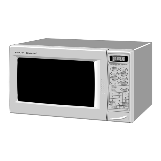
Page 5: Appearance View
R-340A APPEARANCE VIEW 1. Ventilation openings 2. Oven lamp 3. Door hinges 4. Door safety latches 5. See through door 6. Door seals and sealing surfaces 7. Coupling 8. Door open button 9. Touch control panel 10.Digital readout 11.Wave guide cover 12.Power supply cord... -
Page 6: Operation Sequence
R-340A OPERATION SEQUENCE OFF CONDITION opened after the cooking cycle has been interrupted, because the relay RY1 stays closed. Shown in the Closing the door activates all door interlock switches (1st. display is the remaining time. latch switch and 2nd. interlock relay control switch). -
Page 7: Function Of Important Components
R-340A FUNCTION OF IMPORTANT COMPONENTS HIGH VOLTAGE FUSE 0.75A DOOR OPEN MECHANISM The high voltage fuse blows when the high voltage rectifier The door is opened by pushing the open button on the control panel, refer to the Figure D-1. -
Page 8: Servicing
If the water remains cold carry out 3D checks and re- examine the connections to the component being Sharp recommend that wherever possible fault-finding tested. is carried out with the supply disconnected. It may in, some cases, be necessary to connect the supply after... - Page 9 R-340A CK = Check / RE = Replace A B C D E E E G F F H H I L M N O TEST PROCEDURE RE CK CK RE CK CK CK CK CK POSSIBLE CAUSE DEFECTIVE PARTS...
-
Page 10: Test Procedure
R-340A TEST PROCEDURES PROCEDURE COMPONENT TEST LETTER MAGNETRON TEST NEVER TOUCH ANY PART IN THE CIRCUIT WITH YOUR HAND OR AN INSULATED TOOL WHILE THE OVEN IS IN OPERATION. CARRY OUT 3D CHECK. Isolate the magnetron from high voltage circuit by removing all leads connected to filament terminal. - Page 11 R-340A TEST PROCEDURES PROCEDURE COMPONENT TEST LETTER Initial temperature..................... T1 = 11°C Temperature after (42 + 2) = 44 sec..............T2 = 21°C Temperature difference Cold-Warm ............... ∆T1 = 10°C Measured output power The equation is “P = 100 x ∆T” ..........P = 100 x 10°C = 1000 Watts ±...
- Page 12 R-340A TEST PROCEDURES PROCEDURE COMPONENT TEST LETTER HIGH VOLTAGE CAPACITOR TEST CARRY OUT 3D CHECKS. A. Isolate the high voltage capacitor from the circuit. B. Continuity check must be carried out with measuring instrument which is set to the highest resistance range.
- Page 13 R-340A TEST PROCEDURES PROCEDURE COMPONENT TEST LETTER MOTOR WINDING TEST CARRY OUT 3D CHECKS. Disconnect the leads from the motor. Using an ohmmeter, check the resistance between the two terminals as described in the table below. Table: Resistance of Motor...
- Page 14 R-340A TEST PROCEDURES PROCEDURE COMPONENT TEST LETTER TOUCH CONTROL PANEL ASSEMBLY TEST The touch control panel consists of circuits including semiconductors such as LSI, ICs, etc. Therefore, unlike conventional microwave ovens, proper maintenance cannot be performed with only a voltmeter and ohmmeter. In this service manual, the touch control panel assembly is divided into two...
- Page 15 R-340A TEST PROCEDURES PROCEDURE COMPONENT TEST LETTER RELAY TEST Remove the outer case and check voltage between Pin No 3 of the 2-pin connector (A) and the common terminal of the relay RY2 on the power unit with an A.C. voltmeter. The meter should indicate 220 volts, if not check oven circuit.
-
Page 16: Touch Control Panel
R-340A TOUCH CONTROL PANEL ASSEMBLY OUTLINE OF TOUCH CONTROL PANEL The touch control section consists of the following units. 3) Power Source Circuit This circuit generates voltages necessary in the control (1) Key Unit unit from the AC line voltage. - Page 17 R-340A Pin No. Signal Description Terminal not used. 0.12 sec. Signal to sound buzzer (2.0 kHz). H : GND A: key touch sound. L : -5V 2.4 sec. B: Completion sound. H : GND L : -5V Magnetron high-voltage circuit driving signal.
- Page 18 R-340A Pin No. Signal Description Key strobe signal. Signal applied to touch-key section. A pulse signal is input to P44 - P47 terminal while one of G6 line keys on key matrix is touched. Key strobe signal. Signal applied to touch-key section. A pulse signal is input to P44 - P47 terminal while one of G5 line keys on key matrix is touched.
- Page 19 R-340A SERVICING 1. Precautions for Handling Electronic Components For those models, check and repair all the controls This unit uses CMOS LSI in the integral part of the (sensor-related ones included) of the touch control circuits. When handling these parts, the following panel while keeping it connected to the oven.
-
Page 20: Component Replacement And Adjustment Procedure
Please refer to ‘OVEN PARTS, CABINET PARTS, CONTROL PANEL PARTS, DOOR PARTS’, when carrying out any of the following removal procedures: WARNING FOR WIRING and Oven cavity. To prevent an electric shock, take the following 3) Sharp edge: manners. Bottom plate, Oven cavity, Weveguide flange, 1. Before wiring, Chassis support and other metallic plate. - Page 21 R-340A HIGH VOLTAGE RECTIFIER, HIGH VOLTAGE FUSE AND HIGH VOLTAGE CAPACITOR 7. Remove one (1) screw holding capacitor holder to the REMOVAL oven cavity rear plate. 1. CARRY OUT 3D CHECKS. 8. Remove one (1) screw holding high voltage rectifier 2.
- Page 22 4. Where the corners have been snipped off bend corner areas flat. No sharp edge must be evident after removal NOTE: The one (1) screw to fit the turntable motor cover of the turntable motor cover.
- Page 23 R-340A * Do not disfigure the bracket by touching with the 3) Install the fan blade to the shaft of fan motor by pushing pliers. the fan blade with a small, light weight, ball peen 2) Remove the fan blade from the shaft of the fan motor hammer or rubber mallet.
- Page 24 R-340A 1ST. LATCH SWITCH, 2ND. INTERLOCK RERAY CONTROL SWITCH AND MONITOR SWITCH ADJUSTMENT If each switch does not operate properly due to a door toward the oven face. Both results (play in the misadjustment, the following adjustment should be made.
- Page 25 R-340A Upper oven hinge View; front side of door frame 19.Now, door screen is free. Door panel RE-INSTALL 1. Re-install door screen to door frame by reversing the Lower oven hinge procedure of item 18 of "REMOVAL". 2. Re-install the latch spring to the latch head. Re-install the latch spring to the door frame.
-
Page 26: Microwave Measurement
R-340A MICROWAVE MEASUREMENT After adjustment of door latch switches, monitor switch Recommended instruments are: and door are completed individually or collectively, the NARDA 8100 following leakage test must be performed with a survey NARDA 8200 instrument and it must be confirmed that the result meets... -
Page 27: Wiring Diagram
R-340A SCHEMATIC NOTE: CONDITION OF OVEN 1.DOOR CLOSED NOTE: " " indicates components with potentials above 250V. 2.CLOCK APPEARS ON DISPLAY THERMAL CUT-OUT 125˚C (OVEN) NOISE FILTER INTERLOCK COM. N.O. RELAY 2ND INTERLOCK RELAY CONTROL SWITCH THERMAL CUT-OUT 1ST. LATCH 95˚C (MG) - Page 28 R-340A...
-
Page 29: Power Unit Circuit
R-340A LD1 LD2 LD3 LD4 LD5 LD1-LD5 WH-1 R4 27 Q2 2SA933 D1-D4 11ES1 R5 4.7k – AC220V 50Hz R3 750 1/2w Jumper 6 TURNTABLE R6 3.3k MOTOR OVEN LAMP MOTOR N.O. MICRO Q3 KRC243M 10µ/35v – : IF NOT SPECIFIED, 1/4w ± 5%... -
Page 30: Cpu Unit Circuit
R-340A... -
Page 31: Printed Wiring Board
R-340A WH-1 CN - C (C3) (D9) (CN - B) (R1) (J3) DOOR SW (J2) (ZD1) VRS1 (J1) (RY3) LOT NO. Figure S-4. Printed Wiring Board... -
Page 32: Parts List
R-340A PARTS LIST ∆ Note: The parts marked " " may cause undue microwave exposure. The parts marked "*" are used in voltage more than 250V. REF. NO. PART NO. DESCRIPTION Q'TY CODE ELECTRIC PARTS 1- 1 QSW-MA110WRE0 1st. latch switch, 2nd. interlock relay control switch... - Page 33 R-340A ∆ Note: The parts marked " " may cause undue microwave exposure. The parts marked "*" are used in voltage more than 250V. REF. NO. PART NO. DESCRIPTION Q'TY CODE 4- 9 LANGQA452WRP0 Partition angle 4-10 LANGQA454WRP0 MG thermo angle...
- Page 34 R-340A OVEN AND CABINET PARTS 4-18 1-11 1-10 4-10 1-13 4-17 4-16 4-15 4-12 1-17 4-13 4-14 1-12 1-15 4-11 1-14 4-15 1-16...
- Page 35 R-340A 3 - 7 CONTROL PANEL PARTS 3-1E 3 - 4 3 - 2 3 - 7 3 - 3 3 - 1 3-3-1 3 - 7 3 - 5 4-19 DOOR PARTS 3 - 6 MISCELLANEOUS Actual wire harness may be different from illustration.
-
Page 36: Packing And Accessories
R-340A PACKING AND ACCESSORIES TOP PAD ASSEMBLY FPADBA311WRK0 DOOR PROTECTION SHEET SPADPA204WRE0 PLASTIC BAG SSAKHA034WRE0 PRINTING MATTER 6- 2 TURNTABLE TRAY BOTTOM PAD ASSEMBLY FPADBA351WRK0 6- 1 TURNTABLE SUPPORT TRAY PACK INTO THE SPADFA397WRE0 OVEN CAVITY Not replaceable items. PACKING CASE SPAKCC931WRE0 '97SHARP CORP.
Need help?
Do you have a question about the R-340A and is the answer not in the manual?
Questions and answers