
Related Manuals for Miller SuitCase X-TREME 8VS CE


Summary of Contents for Miller SuitCase X-TREME 8VS CE
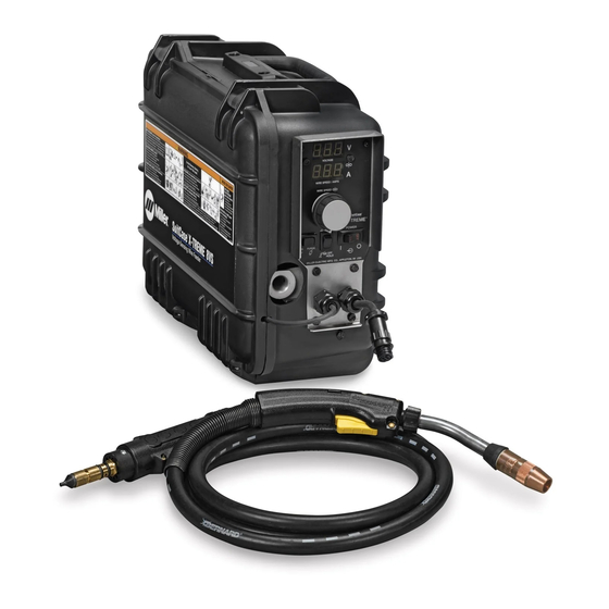
- Page 1 OM-226 288E 2009−06 Processes MIG (GMAW) Welding Flux Cored (FCAW) Welding Description Wire Feeder SuitCase ™ ™ X-TREME 8VS CE And Non-CE Models File: MIG (GMAW) Visit our website at www.MillerWelds.com...
- Page 2 We know you don’t have time to do it any other way. That’s why when Niels Miller first started building arc welders in 1929, he made sure his products offered long-lasting value and superior quality.
-
Page 3: Table Of Contents
TABLE OF CONTENTS SECTION 1 − SAFETY PRECAUTIONS - READ BEFORE USING ........1-1. -
Page 4: Declaration Of Conformity
DECLARATION OF CONFORMITY for European Community (CE marked) products. MILLER Electric Mfg. Co., 1635 Spencer Street, Appleton, WI 54914 U.S.A. declares that the product(s) identified in this declaration conform to the essential requirements and provisions of the stated Council Directive(s) and Standard(s). -
Page 5: Section 1 − Safety Precautions - Read Before Using
SECTION 1 − SAFETY PRECAUTIONS - READ BEFORE USING som _2007−04 Protect yourself and others from injury — read and follow these precautions. 1-1. Symbol Usage DANGER! − Indicates a hazardous situation which, if Indicates special instructions. not avoided, will result in death or serious injury. The possible hazards are shown in the adjoining symbols or explained in the text. - Page 6 D Do not use welder to thaw frozen pipes. FUMES AND GASES can be hazardous. D Remove stick electrode from holder or cut off welding wire at contact tip when not in use. Welding produces fumes and gases. Breathing D Wear oil-free protective garments such as leather gloves, heavy these fumes and gases can be hazardous to your shirt, cuffless trousers, high shoes, and a cap.
-
Page 7: Additional Symbols For Installation, Operation, And Maintenance
1-3. Additional Symbols For Installation, Operation, And Maintenance FIRE OR EXPLOSION hazard. MOVING PARTS can cause injury. D Do not install or place unit on, over, or near D Keep away from moving parts such as fans. combustible surfaces. D Keep all doors, panels, covers, and guards D Do not install unit near flammables. -
Page 8: California Proposition 65 Warnings
1-4. California Proposition 65 Warnings For Gasoline Engines: Welding or cutting equipment produces fumes or gases which contain chemicals known to the State of California to Engine exhaust contains chemicals known to the State of cause birth defects and, in some cases, cancer. (California California to cause cancer, birth defects, or other reproduc- Health &... -
Page 9: Section 2 − Consignes De Sécurité − Lire Avant Utilisation
SECTION 2 − CONSIGNES DE SÉCURITÉ − LIRE AVANT UTILISATION fre_som_2007−04 Se protéger et protéger les autres contre le risque de blessure — lire et respecter ces consignes. 2-1. Symboles utilisés DANGER! − Indique une situation dangereuse qui si on Indique des instructions spécifiques. - Page 10 Il reste une TENSION DC NON NÉGLIGEABLE dans LE SOUDAGE peut provoquer un in les sources de soudage onduleur quand on a cendie ou une explosion. coupé l’alimentation. Le soudage effectué sur des conteneurs fermés tel D Arrêter les convertisseurs, débrancher le courant électrique et que des réservoirs, tambours ou des conduites peu décharger les condensateurs d’alimentation selon les instructions provoquer leur éclatement.
-
Page 11: Dangers Supplémentaires En Relation Avec L'installation, Le Fonctionnement Et La Maintenance
D Protéger les bouteilles de gaz comprimé d’une chaleur excessive, ACCUMULATIONS des chocs mécaniques, des dommages physiques, du laitier, des risquent de provoquer des blessures flammes ouvertes, des étincelles et des arcs. ou même la mort. D Placer les bouteilles debout en les fixant dans un support station- D Fermer l’alimentation du gaz protecteur en cas naire ou dans un porte-bouteilles pour les empêcher de tomber ou de non-utilisation. -
Page 12: Proposition Californienne 65 Avertissements
LES FILS DE SOUDAGE peuvent LE RAYONNEMENT HAUTE FRÉ- provoquer des blessures. QUENCE (H.F.) risque de provoquer des interférences. D Ne pas appuyer sur la gâchette avant d’en avoir reçu l’instruction. D Le rayonnement haute fréquence (H.F.) peut D Ne pas diriger le pistolet vers soi, d’autres per- provoquer des interférences avec les équipe- sonnes ou toute pièce mécanique en enga- ments de radio−navigation et de communica-... -
Page 13: Principales Normes De Sécurité
2-5. Principales normes de sécurité Safety in Welding, Cutting, and Allied Processes, ANSI Standard Z49.1, L4W 5NS (téléphone : 800-463-6727 ou à Toronto 416-747-4044, site de Global Engineering Documents (téléphone : 1-877-413-5184, site Internet : www.csa-international.org). Internet : www.global.ihs.com). Safe Practice For Occupational And Educational Eye And Face Protec- tion, ANSI Standard Z87.1, de American National Standards Institute, Recommended Safe Practices for the Preparation for Welding and Cut- 11 West 43rd Street, New York, NY 10036-8002 (téléphone :... - Page 14 Notes OM-226 288 Page 10...
-
Page 15: Serial Number And Rating Label Location
2-7. Serial Number And Rating Label Location The serial number and rating information for this product is located inside the cover. Use rating label to determine input power requirements and/or rated output. For future reference, write serial number in space provided on back cover of this manual. 2-8. -
Page 16: Section 3 − Installation
SECTION 3 − INSTALLATION 3-1. Specifications Welding Input Type of Wire Feed Wire Max. Wire Power Welding Overall Input Speed Diameter Spool Weight Source Circuit Rating Dimensions Power Range Range Capacity Type Rating *Solid Steel: .023 − .062 in Length: 18 in Constant 50 −... -
Page 17: Installing And Aligning Wire Guide And Drive Rolls
3-4. Installing And Aligning Wire Guide And Drive Rolls Installing Wire Guide And Drive Rolls: Drive Roll Securing Nut Drive Roll Carrier Turn nut one click until lobes of nut line up with lobes of drive roll carrier. Drive Roll Slide drive roll onto drive roll carrier. -
Page 18: Connecting Welding Gun And Voltage Sensing Clamp
3-5. Connecting Welding Gun And Voltage Sensing Clamp Turn Off wire feeder and welding power source. Stop engine on welding generator. Gun Block Gun Securing Knob Gun Power Pin Loosen knob, insert gun end into block. Position power pin as close as possible to drive rolls without touching. -
Page 19: Connecting Weld Cable
3-7. Connecting Weld Cable Turn Off wire feeder and Rear View welding power source. Stop engine on welding generator. User-Supplied Weld Cable Follow wire manufacturer’s recom- From Wire Feeder mendations for weld cable polarity. User-Supplied Male Connector User-Supplied Female Connector Push female connector over male connector, and turn 1/4 turn clock- wise. -
Page 20: Installing And Threading Welding Wire
3-9. Installing And Threading Welding Wire Installing Wire And Adjusting Hub Tension: Hold wire tightly Retaining Nut to keep it from Hub Tension Adjustment Knob unraveling. Remove retaining ring, and install spool so hub pin fits spool hole. Re- install retaining nut. Adjust tension knob so only a slight force is needed to turn spool. -
Page 21: Display Board (Pc20) Dip Switch Settings
3-10. Display Board (PC20) DIP Switch Settings DIP Switch Settings: Display Hold ON Displays will hold their last value for five seconds after the trigger is re- leased. After the hold times out, the Voltage Display will show open circuit voltage. -
Page 22: Section 4 − Operation
SECTION 4 − OPERATION 4-1. Controls With Meters Voltmeter Displays actual arc voltage while welding or open circuit voltage while idle at the feeder. The voltage displayed while welding is an av- erage reading over a time span of 6 to 8 sec- onds. -
Page 23: Controls Without Meters
4-2. Controls Without Meters Wire Speed Control Use control to adjust wire speed within the speed range selected by the wire speed range switch, located on the inner control panel. Maximum wire speed may be limited by arc voltage. Jog/Purge Switch Pressing the Jog switch allows the operator to jog wire without energizing the contactor or gas valve. -
Page 24: Gun Consumables Information
4-3. Gun Consumables Information 235 264-A Notes OM-226 288 Page 20... -
Page 25: Wire Speed Control Settings
4-4. Wire Speed Control Settings Ref. 222 307A Notes OM-226 288 Page 21... -
Page 26: Section 5 − Maintenance & Troubleshooting
SECTION 5 − MAINTENANCE & TROUBLESHOOTING 5-1. Routine Maintenance Disconnect power Maintain more often before maintaining. during severe conditions. 3 Months Replace Damaged Or Replace Damaged Unreadable Gas Hose Labels Repair Or Replace Cracked Cables And Cords 6 Months Clean Blow Out Or Drive Vacuum Inside... -
Page 27: Troubleshooting
5-3. Troubleshooting Trouble Remedy Wire does not feed; open-circuit voltage Check power switch S1 and connections, and replace if necessary. available. Check circuit breaker CB1. Reset CB1. Unit overheated. Allow unit to cool. Check sensing lead connection. Check gun trigger plug connection. Check gun trigger. -
Page 28: Diagnostics
Trouble Remedy Gun trigger is pressed, gas does not If a welding arc is not established in 3 seconds, after the gun trigger is activated, the unit will feed wire flow, wire is not energized, wire feeds. without energizing the contactor or gas valve. If the gun trigger is still activated after two minutes, the wire will stop feeding. -
Page 29: Section 6 − Electrical Diagram
SECTION 6 − ELECTRICAL DIAGRAM 226 637-E Figure 6-1. Circuit Diagram For Wire Feeder OM-226 288 Page 25... -
Page 30: Section 7 − Parts List
SECTION 7 − PARTS LIST Hardware is common and not available unless listed. (Fig 7-3) 1 (Fig 7-2) Figure 7-1. Exploded View Of SuitCase X-TREME 8VS OM-226 288 Page 26... - Page 31 Ref. 804 854-D Item Diagram Part marking Description Quantity Figure 7-1. Complete Assembly ....Fig 7-2 Panel Assembly, Front (Without Meters) ......
- Page 32 Item Diagram Part marking Description Quantity Figure 7-1. Complete Assembly (Continued) ....144 172 Ftg, Hose Brs Barbed M 3/16 Tbg X .250-20 ......
- Page 33 Item Diagram Part marking Description Quantity Figure 7-1. Complete Assembly (Continued) ....226 752 Support, Spool ...........
- Page 34 Hardware is common and not available unless listed. Ref. 804 854-A Figure 7-2. Front Panel Assembly without Meters Item Dia. Part Description Mkgs Quantity Figure 7-2. Front Panel Assembly without Meters (Figure 7-1 Item 15) ... . . 171 007 Knob, Pointer 1.670 Dia X .250 Id W/Set ScrewSplstc .
- Page 35 Hardware is common and not available unless listed. Ref. 804 854-A Figure 7-3. Front Panel Assembly with Meters Item Dia. Part Description Mkgs Quantity Figure 7-3. Front Panel Assembly with Meters (Figure 7-1 Item 15) ... . . 174 991 Knob, Pointer 1.250 Dia X .250 Id W/Spring Clip−.21 .
- Page 36 Table 7-1. Drive Roll & Wire Guide Kits (2 Drive Roll) Base selection of drive rolls upon the following recommended usages: 1. V-Grooved rolls for hard wire. 2. U-Grooved rolls for soft and soft shelled cored wires. 3. U-Cogged rolls for extremely soft shelled wires (usually hard surfacing types). 4.
- Page 37 Notes Start Your Professional Over 80,000 trained 400 Trade Square East, Troy, Ohio 45373 Welding Career Now! since 1930! 1-800-332-9448 www.welding.org...
- Page 38 Notes SOCKET/WRENCH SELECTION TABLE SOCKET/WRENCH SELECTION TABLE (U.S. STANDARD) (METRIC) Specifications Socket or Wrench Size Specifications Socket or Wrench Size U.S. Bolt Decimal Bolt Bolt Decimal Bolt Diameter Equivalent Diameter Equivalent 1/4 in .250 in 3/8 in 7/16 in 6 mm .2362 in 10 mm 10 mm...
- Page 39 Effective January 1, 2009 (Equipment with a serial number preface of LK or newer) This limited warranty supersedes all previous Miller warranties and is exclusive with no other Warranty Questions? guarantees or warranties expressed or implied. LIMITED WARRANTY − Subject to the terms and conditions...
-
Page 40: Options And Accessories
Contact the Delivering Carrier to: File a claim for loss or damage during shipment. For assistance in filing or settling claims, contact your distributor and/or equipment manufacturer’s Transportation Department. © ORIGINAL INSTRUCTIONS − PRINTED IN USA 2009 Miller Electric Mfg. Co. 2009−01...
Need help?
Do you have a question about the SuitCase X-TREME 8VS CE and is the answer not in the manual?
Questions and answers