
Related Manuals for Miller SuitCase 8RC


Summary of Contents for Miller SuitCase 8RC
- Page 1 OM-1500-16 210 243AD 2014−07 Processes MIG (GMAW) Welding Flux Cored (FCAW) Welding Description Wire Feeder SuitCase 8RC CE And Non-CE Models File: MIG (GMAW) Visit our website at www.MillerWelds.com...
- Page 2 We know you don’t have time to do it any other way. That’s why when Niels Miller first started building arc welders in 1929, he made sure his products offered long-lasting value and superior quality.
-
Page 3: Table Of Contents
TABLE OF CONTENTS SECTION 1 − SAFETY PRECAUTIONS - READ BEFORE USING ........1-1. -
Page 4: Declaration Of Conformity
DECLARATION OF CONFORMITY for European Community (CE marked) products. MILLER Electric Mfg. Co., 1635 Spencer Street, Appleton, WI 54914 U.S.A. declares that the product(s) identified in this declaration conform to the essential requirements and provisions of the stated Council Directive(s) and Standard(s). -
Page 5: Section 1 − Safety Precautions - Read Before Using
SECTION 1 − SAFETY PRECAUTIONS - READ BEFORE USING som 2013−09 Protect yourself and others from injury — read, follow, and save these important safety precautions and operating instructions. 1-1. Symbol Usage DANGER! − Indicates a hazardous situation which, if Indicates special instructions. - Page 6 D Remove stick electrode from holder or cut off welding wire at FUMES AND GASES can be hazardous. contact tip when not in use. D Wear body protection made from durable, flame−resistant material Welding produces fumes and gases. Breathing (leather, heavy cotton, wool). Body protection includes oil-free these fumes and gases can be hazardous to your clothing such as leather gloves, heavy shirt, cuffless trousers, high health.
-
Page 7: Additional Symbols For Installation, Operation, And Maintenance
1-3. Additional Symbols For Installation, Operation, And Maintenance FIRE OR EXPLOSION hazard. MOVING PARTS can injure. D Do not install or place unit on, over, or near D Keep away from moving parts such as fans. combustible surfaces. D Keep all doors, panels, covers, and guards D Do not install unit near flammables. -
Page 8: California Proposition 65 Warnings
1-4. California Proposition 65 Warnings Welding or cutting equipment produces fumes or gases This product contains chemicals, including lead, known to which contain chemicals known to the State of California to the state of California to cause cancer, birth defects, or other cause birth defects and, in some cases, cancer. -
Page 9: Section 2 − Consignes De Sécurité − Lire Avant Utilisation
SECTION 2 − CONSIGNES DE SÉCURITÉ − LIRE AVANT UTILISATION fre_som_2013−09 Pour écarter les risques de blessure pour vous−même et pour autrui — lire, appliquer et ranger en lieu sûr ces consignes relatives aux précautions de sécurité et au mode opératoire. 2-1. - Page 10 D Ne pas raccorder plus d’une électrode ou plus d’un câble de D Avoir recours à des écrans protecteurs ou à des rideaux pour masse à une même borne de sortie de soudage. Débrancher le protéger les autres contre les rayonnements les éblouissements câble pour le procédé...
-
Page 11: Dangers Supplémentaires En Relation Avec L'installation, Le Fonctionnement Et La Maintenance
DES PIECES DE METAL ou DES LES BOUTEILLES peuvent exploser si elles sont endommagées. SALETES peuvent provoquer des blessures dans les yeux. Les bouteilles de gaz comprimé contiennent du gaz sous haute pression. Si une bouteille est D Le soudage, l’écaillement, le passage de la endommagée, elle peut exploser. - Page 12 LES CHARGES ÉLECTROSTATI- RAYONNEMENT HAUTE QUES peuvent endommager les cir- FRÉQUENCE (H.F.) risque cuits imprimés. provoquer des interférences. D Établir la connexion avec la barrette de terre D Le rayonnement haute fréquence (H.F.) peut avant de manipuler des cartes ou des pièces. provoquer des interférences avec les équi- D Utiliser des pochettes et des boîtes antista- pements de radio−navigation et de com-...
-
Page 13: Proposition Californienne 65 Avertissements
2-4. Proposition californienne 65 Avertissements Les équipements de soudage et de coupage produisent des Ce produit contient des produits chimiques, notamment du fumées et des gaz qui contiennent des produits chimiques plomb, dont l’État de Californie reconnaît qu’ils provoquent dont l’État de Californie reconnaît qu’ils provoquent des mal- des cancers, des malformations congénitales ou d’autres formations congénitales et, dans certains cas, des cancers. - Page 14 OM-1500−16 Page 10...
-
Page 15: Section 3 − Definitions
SECTION 3 − DEFINITIONS 3-1. Additional Safety Symbols And Definitions Some symbols are found only on CE products. Warning! Watch Out! There are possible hazards as shown by the symbols. Safe1 2012−05 Do not discard product (where applicable) with general waste. Reuse or recycle Waste Electrical and Electronic Equipment (WEEE) by disposing at a designated collection facility. -
Page 16: Miscellaneous Symbols And Definitions
Do not weld on drums or any closed containers. Safe64 2012−06 Do not remove or paint over (cover) the label. Safe20 2012−05 Drive rolls can injure fingers. Safe32 2012−05 Welding wire and drive parts are at welding voltage during operation − keep hands and metal objects away. Safe33 2012−05 Wear hat and safety glasses. -
Page 17: Section 4 − Installation
SECTION 4 − INSTALLATION 4-1. Serial Number And Rating Label Location The serial number and rating information for this product is located inside the cover. Use rating label to determine input power requirements and/or rated output. For future reference, write serial number in space provided on back cover of this manual. 4-2. -
Page 18: 14-Pin Plug Information
4-5. 14-Pin Plug Information Pin* Pin Information 24 volts AC with respect to socket G. Contact closure to A completes 24 volts AC contactor control circuit. Circuit common for 24 volts AC circuit. +10 volts DC input from power source to wire feeder with respect to socket D. Remote control circuit common. -
Page 19: Installing And Aligning Wire Guide And Drive Rolls
4-8. Installing And Aligning Wire Guide And Drive Rolls Installing Wire Guide And Drive Rolls: Drive Securing Roll Nut Drive Roll Carrier Turn nut one click until lobes of nut line up with lobes of drive roll carrier. Drive Roll Slide drive roll onto drive roll carrier. -
Page 20: Connecting Welding Gun
4-9. Connecting Welding Gun Turn Off wire feeder and welding power source. Stop engine on welding generator. Gun Securing Knob Gun Block Gun Power Pin Power Pin Groove Gun Locking Tab Loosen knob, insert gun end into block. Position power pin as close as possible to drive rolls without touching. -
Page 21: Connecting Shielding Gas
4-10. Connecting Shielding Gas NOTICE − This feeder has a shield- ing gas filter that requires special attention when cleaning. See Sec- tion 6-3 for proper cleaning instruc- tions. Gas Hose With 5/8-18 Right-hand Thread Fittings (Customer Supplied) Rear View Shielding Gas Cylinder Shielding gas pressure not to exceed 100 psi (689 kPa). -
Page 22: Weld Cable Sizes
**Weld cable size (AWG) is based on either a 4 volts or less drop or a current density of at least 300 circular mils per ampere. ( ) = mm for metric use ***For distances longer than those shown in this guide, call a factory applications rep. at 920-735-4505 (Miller) or 1-800-332-3281 (Hobart). Ref. S-0007-K 2013−09 OM-1500-16 Page 18... -
Page 23: Installing And Threading Welding Wire
4-13. Installing And Threading Welding Wire Installing Wire And Adjusting Hub Tension: Hold wire tightly Retaining Nut to keep it from Hub Tension Adjustment Nut unraveling. Remove retaining ring, and install spool so hub pin fits spool hole. Re- install retaining nut. Adjust tension knob so only a slight force is needed to turn spool. -
Page 24: Section 5 − Operation
SECTION 5 − OPERATION 5-1. Controls Power Control Switch Snap-In Blank Voltage Control Wire Speed Control Use control to adjust wire speed within range selected by switch. Purge Switch Press switch to momentarily ener- gize gas solenoid and purge air from gun, and to adjust shielding gas regulator. -
Page 25: Controls For Meter (Optional)
5-2. Controls For Meter (Optional) Power Control Switch Trigger Hold Switch Depress the left part of the switch (turns trigger hold On) to weld with- out holding gun trigger throughout the weld cycle. To start weld, press and release gun trigger. To end weld, press and release gun trigger. -
Page 26: Setting Digital Meter Board Pc4 Dip Switches
5-3. Setting Digital Meter Board PC4 DIP Switches Front Meter Panel S1 DIP Switch S2 DIP Switch If the DIP switches are set to a Meter Hold (ON) position, the meter value will hold 5 seconds after gun is trig- gered. -
Page 27: Gun Consumables Information
5-4. Gun Consumables Information 235 264-A Notes OM-1500-16 Page 23... -
Page 28: Section 6 − Maintenance & Troubleshooting
SECTION 6 − MAINTENANCE & TROUBLESHOOTING 6-1. Routine Maintenance Maintain more often Disconnect power before maintaining. during severe conditions. 3 Months Replace Damaged Or Replace Damaged Unreadable Gas Hose Labels Repair Or Replace Cracked Cables And Cords 6 Months Clean Blow Out Or Drive Vacuum Inside... -
Page 29: Cleaning Debris From Shielding Gas Filter Fitting
6-3. Cleaning Debris From Shielding Gas Filter Fitting Disconnect power before maintaining. Shielding Gas Filter Fitting Remove fitting from gas valve on Rear View of Feeder back panel of feeder. Blow compressed air through the threaded male end of fitting to dis- lodge debris from internal mesh screen. - Page 30 Trouble Remedy Wire feeds as soon as power is applied. Check gun trigger. See gun Owner’s Manual. Wire does not feed until trigger is Check for short between gun trigger leads and weld cable. Repair or replace gun trigger leads. pressed but continues to feed after trig- ger is released.
-
Page 31: Section 7 − Electrical Diagrams
SECTION 7 − ELECTRICAL DIAGRAMS 251 096-A Figure 7-1. Circuit Diagram For Wire Feeder OM-1500-16 Page 27... -
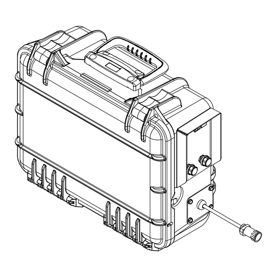
Page 32: Section 8 − Parts List
SECTION 8 − PARTS LIST Hardware is common and not available unless listed. 1 (Fig 8-2) 2 (Fig 8-3) Ref. 246 723-C Figure 8-1. Complete Assembly OM-1500-16 Page 28... - Page 33 Item Dia. Part Description Mkgs. Quantity Figure 8-1. Complete Assembly . . . Fig 8-2 . . . 235 843 Panel Assy, Front Without Meters ........
- Page 34 Item Dia. Part Description Mkgs. Quantity Figure 8-1. Complete Assembly (Continued) ... . . 254 843 Nut, PG21 1.50Hex X ‘.375H Aluminum ......
- Page 35 Item Dia. Part Description Mkgs. Quantity Figure 8-1. Complete Assembly (Continued) ....115 090 Housing Plug+Pins, (Service Kit) ........
- Page 36 Hardware is common and not available unless listed. Ref. 251 169-C Figure 8-2. Front Panel Assembly without Meters Item Dia. Part Description Mkgs Quantity Figure 8-2. Front Panel Assembly without Meters (Figure 8-1 Item 1) R1, R50 208 399 Pot, Cp Std Slot 1T 2. W 10K Linear W/Frict Tabs .
- Page 37 Hardware is common and not available unless listed. Ref. 805 133-C Figure 8-3. Front Panel Assembly with Meters Item Dia. Part Description Mkgs Quantity Figure 8-3. Front Panel Assembly with Meters (8-1 Item 2) ..236 698 Circuit Card Assy, Meter W/Amps (4) .
- Page 38 Figure 8-4. Drive Roll And Wire Guide Kits Base selection of drive rolls upon the following recommended usages: 1. V-Grooved rolls for hard wire. 2. U-Grooved rolls for soft and soft shelled cored wires. 3. U-Cogged rolls for extremely soft shelled wires (usually hard surfacing types). 4.
- Page 39 Effective January 1, 2014 (Equipment with a serial number preface of ME or newer) This limited warranty supersedes all previous Miller warranties and is exclusive with no other guarantees or warranties expressed or implied. Warranty Questions? LIMITED WARRANTY − Subject to the terms and conditions below, 6 Months —...
- Page 40 Contact the Delivering Carrier to: File a claim for loss or damage during shipment. For assistance in filing or settling claims, contact your distributor and/or equipment manufacturer’s Transportation Department. © ORIGINAL INSTRUCTIONS − PRINTED IN USA 2014 Miller Electric Mfg. Co. 2014−01...
Need help?
Do you have a question about the SuitCase 8RC and is the answer not in the manual?
Questions and answers