Table of Contents
Advertisement
Visit our website at
www.MillerWelds.com
Deltaweld Series
302, 452, 652 (60 Hz), 402, 602, 852 (50/60 Hz)
OM-223
November 2003
Processes
Gas Metal Arc (MIG) Welding
Flux Cored Arc Welding
Submerged Arc Welding
(452/652 Only)
Air Carbon Arc Cutting
and Gouging (452/652 Only)
Description
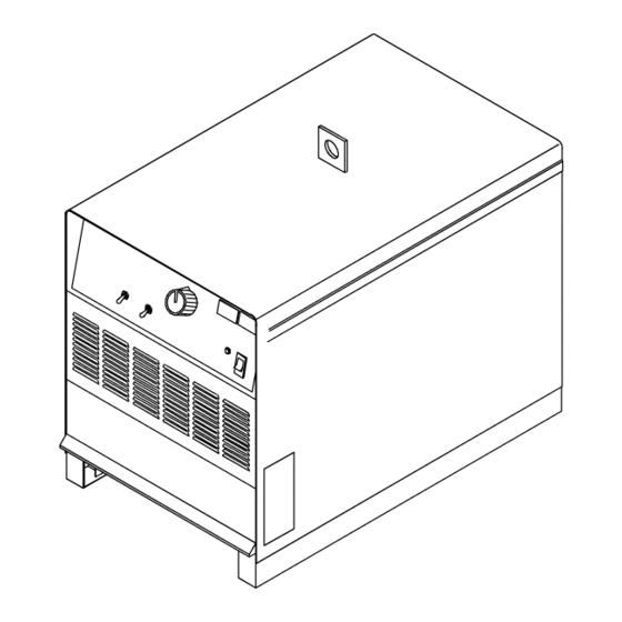
Arc Welding Power Source
R
166 538AE
Advertisement
Table of Contents
Troubleshooting

Related Manuals for Miller Deltaweld 652


Summary of Contents for Miller Deltaweld 652
- Page 1 OM-223 166 538AE November 2003 Processes Gas Metal Arc (MIG) Welding Flux Cored Arc Welding Submerged Arc Welding (452/652 Only) Air Carbon Arc Cutting and Gouging (452/652 Only) Description Arc Welding Power Source Deltaweld Series 302, 452, 652 (60 Hz), 402, 602, 852 (50/60 Hz) Visit our website at www.MillerWelds.com...
- Page 2 We know you don’t have time to do it any other way. That’s why when Niels Miller first started building arc welders in 1929, he made sure his products offered long-lasting value and superior quality.
-
Page 3: Table Of Contents
TABLE OF CONTENTS SECTION 1 − SAFETY PRECAUTIONS - READ BEFORE USING ........1-1. - Page 4 Declaration of Conformity For European Community (CE) Products NOTE This information is provided for units with CE certification (see rating label on unit.) Miller Electric Mfg. Co. Manufacturer’s Name: 1635 W. Spencer Street Manufacturer’s Address: Appleton, WI 54914 USA Deltaweld 402, 602, And 852...
-
Page 5: Section 1 − Safety Precautions - Read Before Using
SECTION 1 − SAFETY PRECAUTIONS - READ BEFORE USING som _8/03 1-1. Symbol Usage Means Warning! Watch Out! There are possible hazards with this procedure! The possible hazards are shown in the adjoining symbols. This group of symbols means Warning! Watch Out! possible Y Marks a special safety message. - Page 6 ARC RAYS can burn eyes and skin. BUILDUP OF GAS can injure or kill. D Shut off shielding gas supply when not in use. Arc rays from the welding process produce intense D Always ventilate confined spaces or use visible and invisible (ultraviolet and infrared) rays that can burn eyes and skin.
-
Page 7: Additional Symbols For Installation, Operation, And Maintenance
1-3. Additional Symbols For Installation, Operation, And Maintenance FIRE OR EXPLOSION hazard. MOVING PARTS can cause injury. D Do not install or place unit on, over, or near D Keep away from moving parts such as fans. combustible surfaces. D Keep all doors, panels, covers, and guards D Do not install unit near flammables. -
Page 8: Principal Safety Standards
1-5. Principal Safety Standards Safety in Welding, Cutting, and Allied Processes, ANSI Standard Z49.1, Boulevard, Rexdale, Ontario, Canada (phone: from American Welding Society, 550 N.W. LeJeune Rd, Miami FL 33126 800−463−6727 or in Toronto 416−747−4044, website: www.csa−in- (phone: 305-443-9353, website: www.aws.org). ternational.org). -
Page 9: Section 2 − Consignes De Sécurité − À Lire Avant Utilisation
SECTION 2 − CONSIGNES DE SÉCURITÉ − À LIRE AVANT UTILISATION som_fre 8/03 2-1. Signification des symboles Signifie « Mise en garde. Faire preuve de vigilance. » Cette procédure présente des risques identifiés par les symboles adjacents aux directives. Ce groupe de symboles signifie « Mise en garde. Faire preuve de vigi- Y Identifie un message de sécurité... - Page 10 LES RAYONS DE L’ARC peuvent cau- LES ACCUMULATIONS DE GAZ peu- ser des brûlures oculaires et cuta- vent causer des blessures ou même nées. la mort. Le rayonnement de l’arc génère des rayons visibles et D Couper l’alimentation en gaz protecteur en cas de invisibles intenses (ultraviolets et infrarouges) suscep- non utilisation.
-
Page 11: Autres Symboles Relatifs À L'installation, Au Fonctionnement Et À L'entretien De L'appareil
2-3. Autres symboles relatifs à l’installation, au fonctionnement et à l’entretien de l’appareil. Risque D’INCENDIE OU D’EXPLO- LES ORGANES MOBILES peuvent SION causer des blessures. D Ne pas placer l’appareil sur une surface inflam- D Se tenir à l’écart des organes mobiles comme les mable, ni au−dessus ou à... -
Page 12: Principales Normes De Sécurité
2-4. Principales normes de sécurité Safety in Welding, Cutting, and Allied Processes, norme ANSI Z49.1, Rexdale, Rexdale (Ontario) Canada M9W 1R3 (téléphone : (800) de l’American Welding Society, 550 N.W. LeJeune Rd, Miami FL 33126 463−6727 ou à Toronto : (416) 747−4044, site Web : www.csa−interna- (téléphone : (305) 443−9353, site Web : www.aws.org). -
Page 13: Section 3 − Definitions
SECTION 3 − DEFINITIONS 3-1. General Precautionary Label Warning! Watch Out! There are possible hazards as shown by the symbols. Electric shock from welding electrode or wiring can kill. 1.1 Wear dry insulating gloves. Do not touch electrode with bare hand. Do not wear wet or damaged gloves. -
Page 14: Input Connection Label
3-2. Input Connection Label 1/96 Warning! Watch Out! There are possible hazards as shown by the symbols. Electric shock from wiring can kill. Disconnect input plug or power before working on machine. Read the Owner’s Manual before working on this machine. -
Page 15: Manufacturer's Rating Labels For Ce Products
3-5. Manufacturer’s Rating Labels For CE Products Match label to one on unit. See Section 4-4. OM-223 Page 11 Return To Table Of Contents... -
Page 16: Symbols And Definitions
3-6. Symbols And Definitions Note Some symbols are found only on CE products. Voltage Control/ Gas Metal Arc Amperes Temperature Panel Welding (GMAW) Output Circuit Breaker Remote Positive High Positive Low Negative Weld Inductance Weld Inductance Weld Input Output Terminal Output Terminal Output Terminal Protective Earth... -
Page 17: Section 4 − Installation
SECTION 4 − INSTALLATION 4-1. Specifications Amperes Input at Rated Load Output, 50 or 60 Hz, Rated Voltage Three-Phase Welding Welding Range Range OCV DC Rating 200 V 230 V 380 V 400 V 440 V 460 V 575 V Output Model 300 A @ 32... -
Page 18: Volt-Ampere Curves
4-3. Volt-Ampere Curves Volt-ampere curves show mini- mum and maximum voltage and amperage output capabilities of unit. Curves of other settings fall be- tween curves shown. A. 300 Amp Model B. 450 Amp Model C. 650 Amp Model va_curve1 − 4/95 − ST-171 224 / ST-171 225 / ST-171 226 OM-223 Page 14 Return To Table Of Contents... -
Page 19: Selecting A Location
4-4. Selecting A Location Lifting Eye Lifting Forks Use lifting eye or lifting forks to move unit. Movement If using lifting forks, extend forks beyond opposite side of unit. Rating Label (Non CE Models Only) Use rating label to determine input power needs. -
Page 20: Dimensions And Weights
4-5. Dimensions And Weights Dimensions 300 Amp Models 450 Amp Models 650 Amp Models 30 in (762 mm) including lift eye 30 in (762 mm) including lift eye 30 in (762 mm) including lift eye 23 in (585 mm) 23 in (585 mm) 23 in (585 mm) 30-1/2 in (775 mm) including strain relief 38 in (966 mm) including strain relief... -
Page 21: 115 Vac Receptacle And Circuit Breakers
4-7. 115 VAC Receptacle And Circuit Breakers Y Turn Off power before con- necting to receptacle. 115 V 15 A AC Receptacle Power is shared between RC9 and Remote 14 receptacle RC8 (see Section 4-9). Circuit Breaker CB1 Circuit Breaker CB2 CB1 protects the 115 volts ac por- tion of RC8 and RC9 from overload. -
Page 22: Remote 14 Receptacle Rc8
4-9. Remote 14 Receptacle RC8 Y Turn off power before con- necting to receptacle. Remote 14 Receptacle RC8 Connect feeder to RC8. C L N Ref. ST-800 166-D / Ref. S-0004-A 4-10. Remote 14 Receptacle RC8 Information Socket Information 24 volts ac. Protected by circuit breaker CB2. 24 VOLTS AC 24 VOLTS AC Contact closure to A completes 24 volts ac contactor control circuit. -
Page 23: Electrical Service Guide
4-11. Electrical Service Guide 60 Hertz Models 300 Amp Model 450 Amp Model 650 Amp Model Input Voltage Input Amperes At Rated Output Max Recommended Standard Fuse Rating In Amperes Time-Delay Normal Operating 3 Min Input Conductor Size In AWG/Kcmil Max Recommended Input Conductor Length In Feet (Meters) (34) -
Page 24: Placing Jumper Links
4-12. Placing Jumper Links Y Disconnect and lockout/tag- out input power before installing or moving jumper links. Check input voltage available at site. Jumper Link Label Check label − only one is on unit. Jumper Links Move jumper links to match input voltage. -
Page 25: Connecting Input Power
4-13. Connecting Input Power Y Disconnect and lockout/tagout in- put power before connecting input conductors from unit. Y Have only qualified persons make this installation. See rating label on unit and check input voltage available at site. = GND/PE Earth Ground Line Disconnect Device Input Conductors Grounding Conductor... -
Page 26: Section 5 − Operation
SECTION 5 − OPERATION 5-1. Controls (Non CE Models) Ref. ST-162 503-C Voltage Adjustment Control Power Switch With Indicator Light For front panel control of output, place switch in Panel position. For remote control of output, Turn control clockwise to increase voltage. High Temperature Shutdown Light place switch in Remote position, and connect Voltmeter value changes as control knob is... -
Page 27: Section 6 − Maintenance & Troubleshooting
SECTION 6 − MAINTENANCE & TROUBLESHOOTING 6-1. Routine Maintenance Y Disconnect input power before maintaining. 3 Months Clean Repair or Replace tighten weld replace unreadable terminals. cracked labels. weld cable. 6 Months Blow out or vacuum inside. During heavy service, clean monthly 6-2. -
Page 28: Troubleshooting Table
6-4. Troubleshooting Table Trouble Remedy No weld output; unit completely Place line disconnect switch in On position (see Section 4-13). inoperative. Check fuse F1, and replace if necessary (see Section 6-2). Check and replace line fuse(s), if necessary, or reset circuit breaker (see Section 4-13). Check for proper input power connections (see Section 4-13). - Page 29 Notes OM-223 Page 25 Return To Table Of Contents...
-
Page 30: Section 7 − Electrical Diagram
SECTION 7 − ELECTRICAL DIAGRAM Figure 7-1. Circuit Diagram OM-223 Page 26 Return To Table Of Contents... - Page 31 207 211-A Return To Table Of Contents OM-223 Page 27...
-
Page 32: Section 8 − Parts List
SECTION 8 − PARTS LIST Hardware is common and not available unless listed. ST-800 992-G Figure 8-1 Main Assembly (452 Model Illustrated) OM-223 Page 28 Return To Table Of Contents... - Page 33 Quantity Model Item Dia. Part Mkgs. Description 302 452 652 Figure 8-1 Main Assembly (452 Model Illustrated) ....+179 430 PANEL, side ......... . .
- Page 34 Quantity Model Item Dia. Part Mkgs. Description 302 452 652 Figure 8-1 Main Assembly (452 Model Illustrated) (continued) ..TP1,2 . . . 175 405 THERMOSTAT, NC (Included w/T1) ..... . .
- Page 35 Quantity Model Item Dia. Part Mkgs. Description 302 452 652 Figure 8-2 Panel, Front w/Components (Fig 8-1 Item 31) ....159 863 ELECTRONICS BOX ........
- Page 36 Quantity Model Item Dia. Part Mkgs. Description 302 452 652 Figure 8-2 Panel, Front w/Components (Fig 8-1 Item 31) (continued) ..181 245 TERMINAL, pwr output red ......
- Page 37 Item Dia. Part Mkgs. Description Quantity 175 070 Figure 8-3 Rectifier, Si Diode (302 Model) (Fig 8-1 Item 32) ..C7-12 ..048 420 CAPACITOR, cer disc .01uf 1000VDC ......
- Page 38 Item Dia. Part Mkgs. Description Quantity Figure 8-5 Panel, Rear w/Components (Fig 8-1 Item 19) ....173 283 CHAMBER, plenum 14 in ........
- Page 41 Effective January 1, 2003 (Equipment with a serial number preface of “LC” or newer) This limited warranty supersedes all previous Miller warranties and is exclusive with no other Warranty Questions? guarantees or warranties expressed or implied. Call LIMITED WARRANTY − Subject to the terms and conditions Induction Heating Coils and Blankets below, Miller Electric Mfg.
-
Page 42: Options And Accessories
Distributor Address City State For Service Call 1-800-4-A-Miller or see our website at www.MillerWelds.com to locate a DISTRIBUTOR or SERVICE AGENCY near you. Always provide Model Name and Serial/Style Number. Contact your Distributor for: Welding Supplies and Consumables Options and Accessories...
Need help?
Do you have a question about the Deltaweld 652 and is the answer not in the manual?
Questions and answers