Table of Contents
Advertisement
Quick Links
Download this manual
See also:
Owner's Manual
Advertisement
Table of Contents
Troubleshooting

Related Manuals for Miller Spectrum 875


Summary of Contents for Miller Spectrum 875
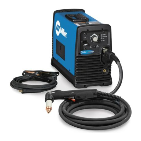
- Page 1 OM-264259C 2018−03 Processes Air Plasma Cutting and Gouging Description Air Plasma Cutter Spectrum 875 And XT60 Torch File: Plasma Cutters For product information, Owner’s Manual translations, and more, visit www.MillerWelds.com...
- Page 2 We know you don’t have time to do it any other way. That’s why when Niels Miller first started building arc welders in 1929, he made sure his products offered long-lasting value and superior quality.
-
Page 3: Table Of Contents
Full KVA Receptacle (NEMA 14-50R) Using Adapter Cord (Part No. 300158) ....5-9. Wiring Optional 240 Volt Plug (119172) For Connection To Miller Bobcat, Trailblazer Or Hobart Champion 10,000 . - Page 4 TABLE OF CONTENTS SECTION 7 − MECHANIZED OPERATION ........... . . 7-1.
-
Page 5: Section 1 − Safety Precautions - Read Before Using
SECTION 1 − SAFETY PRECAUTIONS - READ BEFORE USING pom_2018−01 Protect yourself and others from injury — read, follow, and save these important safety precautions and operating instructions. 1-1. Symbol Usage DANGER! − Indicates a hazardous situation which, if Indicates special instructions. not avoided, will result in death or serious injury. -
Page 6: Electric Shock Can Kill
FUMES AND GASES can be hazardous ELECTRIC SHOCK can kill. Cutting produces fumes and gases. Breathing SIGNIFICANT DC VOLTAGE exists in these fumes and gases can be hazardous to inverter power sources AFTER the re- your health. moval of input power. Keep your head out of the fumes. -
Page 7: Additional Symbols For Installation, Operation, And Maintenance
1-3. Additional Symbols For Installation, Operation, And Maintenance FALLING EQUIPMENT can injure. HOT PARTS can burn. D Use lifting eye to lift unit only, NOT running D Do not touch hot parts bare handed. gear, gas cylinders, or any other accessories. D Allow cooling period before working on D Use correct procedures and equipment of ade- equipment. -
Page 8: California Proposition 65 Warnings
1-4. California Proposition 65 Warnings WARNING: This product can expose you to chemicals in- cluding lead, which are known to the state of California to cause cancer and birth defects or other reproductive harm. For more information, go to www.P65Warnings.ca.gov . 1-5. -
Page 9: Section 2 − Consignes De Sécurité − Lire Avant Utilisation
SECTION 2 − CONSIGNES DE SÉCURITÉ − LIRE AVANT UTILISATION pom_2018−01_fre Pour écarter les risques de blessure pour vous−même et pour autrui — lire, appliquer et ranger en lieu sûr ces consignes relatives aux précautions de sécurité et au mode opératoire. 2-1. - Page 10 D Ne touchez pas aux pièces électriques sous tension. Risque de blessure en cas D Portez des gants isolants et des vêtements de protection secs et D’EXPLOSION DES PIÈCES. sans trous. D Mise sous tension, toute pièce défectueuse D Isolez−vous de la pièce à couper et du sol en utilisant des housses des sources d’alimentation de l’inverseur peut ou des tapis assez grands afin d’éviter tout contact physique avec exploser ou faire exploser d’autres pièces.
- Page 11 corps comporte des vêtements sans huile comme par ex. des LES FUMÉES ET LES GAZ peuvent gants de cuir, une chemise solide, des pantalons sans revers, des être dangereux. chaussures hautes et une casquette. Le coupage produit des vapeurs et des gaz. D Ne pointez pas le chalumeau en direction de votre corps ni de la Respirer ces vapeurs et ces gaz peut être pièce à...
-
Page 12: Dangers Supplémentaires En Relation Avec L'installation, Le Fonctionnement Et La Maintenance
2-3. Dangers supplémentaires en relation avec l’installation, le fonctionnement et la maintenance PIÈCES CHAUDES peuvent Danger D’EXPLOSION provoquer des brûlures. D’HYDROGÈNE. D Ne pas toucher des parties chaudes à mains D Lors du coupage d’aluminium sous l’eau ou avec de l’eau touchant le dessous de l’alumi- nues. -
Page 13: Proposition Californienne 65 Avertissements
D Demander seulement à des personnes qualifiées familiarisées LE COUPAGE Ã L’ARC peut causer avec des équipements électroniques de faire fonctionner des interférence. l’installation. D L’utilisateur est tenu de faire corriger rapidement par un électricien D L’énergie électromagnétique peut gêner le qualifié... -
Page 14: Section 3 − Definitions
SECTION 3 − DEFINITIONS 3-1. Additional Safety Symbols And Definitions Some symbols are found only on CE products. Warning! Watch Out! There are possible hazards as shown by the symbols. Safe1 2012−05 When power is applied failed parts can explode or cause other parts to explode. Safe26 2012−05 3-2. -
Page 15: Section 4 − Specifications
A complete Parts List is available at www.MillerWelds.com SECTION 4 − SPECIFICATIONS 4-1. Serial Number And Rating Label Location The serial number and rating information for this product is located on the bottom. Use rating label to determine input power requirements and/or rated output. -
Page 16: Environmental Specifications
A complete Parts List is available at www.MillerWelds.com 4-3. Environmental Specifications A. IP Rating IP Rating IP23CS This equipment is designed for outdoor use. It may be stored, but is not intended to be used for cutting outside during precipitation unless sheltered. -
Page 17: Torch Dimensions
A complete Parts List is available at www.MillerWelds.com 4-5. Torch Dimensions Hand-Held Torch 8.75 in. (222 mm) 1.5 in. 1.1875 in. (38 mm) (30 mm) Ref. 253 554-A Long Body 15.594 in. (396 mm) long body Machine Torch 2.141 in. (54 mm) 1.0625 in. -
Page 18: Section 5 − Installation
A complete Parts List is available at www.MillerWelds.com SECTION 5 − INSTALLATION 5-1. Selecting a Location Do not move or operate unit where it could tip. Movement Location And Airflow Special installation may be required where gasoline or volatile liquids are present − see NEC Article 511 or CEC Section 20. -
Page 19: Connecting Work Clamp And Gas/Air Supply
A complete Parts List is available at www.MillerWelds.com 5-2. Connecting Work Clamp and Gas/Air Supply Work Clamp Workpiece Connect work clamp to portion of workpiece that does not fall away after being cut. Connect work clamp to a clean, paint-free location on workpiece, as close to cutting area as possible. -
Page 20: Connecting And Disconnecting Torch
A complete Parts List is available at www.MillerWelds.com 5-3. Connecting And Disconnecting Torch Turn off power source and disconnect input power. Torch Connector Quick Connect Collar Nipple Receptacle Securing Pin To connect torch: Push torch connector onto receptacle and quick connect until collar secures nipple. -
Page 21: Electrical Service Guide
A complete Parts List is available at www.MillerWelds.com 5-5. Electrical Service Guide Elec Serv 2017−01 Failure to follow these electrical service guide recommendations could create an electric shock or fire hazard. These recommenda- tions are for a dedicated circuit sized for the rated output and duty cycle of the welding power source. In dedicated circuit installations, the National Electrical Code (NEC) allows the receptacle or conductor rating to be less than the rating of the circuit protection device. -
Page 22: Selecting A Location And Connecting Input Power
A complete Parts List is available at www.MillerWelds.com 5-7. Selecting A Location And Connecting Input Power =GND/PE Earth Ground Install conductors into a deenergized line disconnect device. 230 VAC, 1 Input13 2015−08 Ref. 805 159-A / 805 162-A OM-264259 Page 18... - Page 23 A complete Parts List is available at www.MillerWelds.com 5-7. Connecting 1-Phase Input Power (Continued) Plug (NEMA Type 6-50P) Connect green or green/yellow grounding Installation must meet all National and conductor to disconnect device grounding Local Codes − have only qualified per- Receptacle terminal first.
-
Page 24: Connecting Plasma Cutter To Miller Or Hobart Generator Equipped With A
A complete Parts List is available at www.MillerWelds.com 5-8. Connecting Plasma Cutter To Miller Or Hobart Generator Equipped With A Full KVA Receptacle (NEMA 14-50R) Using Adapter Cord (Part No. 300158) Adapter Cord Plasma Cutter Plug Generator Receptacle Use adapter cord to connect... -
Page 25: Wiring Optional 240 Volt Plug (119172) For Connection To Miller Bobcat, Trailblazer
A complete Parts List is available at www.MillerWelds.com 5-9. Wiring Optional 240 Volt Plug (119172) For Connection To Miller Bobcat, Trailblazer Or Hobart Champion 10,000 Input And Grounding Conductors Plug Wired for 240 V, 2-Wire 3 (Not Used) Load Tools Needed:... -
Page 26: Generator Settings For Plasma Cutter Operation
A complete Parts List is available at www.MillerWelds.com 5-10. Generator Settings For Plasma Cutter Operation Engine Control Switch must be set at Set generator Fine Adjustment Control to 10 “RUN” position − not “RUN/IDLE”. for maximum auxiliary power, if applicable. The peak KW at arc stretch of this plasma power source is 15.5 KW. -
Page 27: Section 6 − Operation
A complete Parts List is available at www.MillerWelds.com SECTION 6 − OPERATION 6-1. Controls Ref. 234 155-A Output Control Cut/Gouge Switch Use only clean, dry air with 90 to 120 psi Use control to set cutting output. Place switch in appropriate position for de- (621 to 827 kPa) pressure. -
Page 28: Consumables Storage Compartment
A complete Parts List is available at www.MillerWelds.com 6-2. Consumables Storage Compartment Consumables Storage Compartment This compartment provides convenient access to consumables and parts. Rear of Unit Ref. 805 160-A 6-3. Trigger Safety Lock Trigger Trigger Locked Trigger Unlocked Ref. 253 554-A OM-264259 Page 24... -
Page 29: Plasma Cutting System Practices
A complete Parts List is available at www.MillerWelds.com 6-4. Plasma Cutting System Practices The pilot arc starts immediately when trigger is pressed. GOUGE Always connect work clamp to a clean, DO NOT start pilot arc without cutting or Set switch to either cut or gouge paint-free location on workpiece, as close to gouging as this shortens the service life depending on desired process. -
Page 30: Sequence Of Cutting Operation
A complete Parts List is available at www.MillerWelds.com 6-5. Sequence Of Cutting Operation GOUGE Connect work clamp to a clean, paint-free Unit automatically regulates pressure to 75 psi location on workpiece, as close to cutting (517 kPa) for cutting. area as possible. Connect work clamp to portion of workpiece that does not fall away after being cut. -
Page 31: Sequence Of Gouging Operation
A complete Parts List is available at www.MillerWelds.com 6-6. Sequence Of Gouging Operation GOUGE Unit automatically regulates pressure Trigger pilot arc once to 60 psi (413 kPa) for gouging. before starting to gouge. Connect work clamp to a clean, paint-free location on workpiece, as close to cutting area as possible. -
Page 32: Sequence Of Piercing Operation
A complete Parts List is available at www.MillerWelds.com 6-7. Sequence Of Piercing Operation The pilot arc starts immediately when trigger is pressed. Recommended maximum piercing capacity is 7/16 in (11 mm). GOUGE ° Unit automatically regulates pressure to 75 psi (517 kPa) for cutting. Connect work clamp to a clean, paint-free location on workpiece, as Hold torch at approximately 45°... -
Page 33: Cutting Speed
A complete Parts List is available at www.MillerWelds.com 6-8. Cutting Speed Mild Steel Material Thickness Recommended Cut Speeds Arc Current Inches mm/min 18ga (0.05) 11,557 16ga (0.06) 11,125 14ga (0.08) 6985 1/8 (0.13) 4953 3/16 (0.19) 2311 1/4 (0.25) 1549 1/4 (0.25) 2540 3/8 (0.38) -
Page 34: Section 7 − Mechanized Operation
A complete Parts List is available at www.MillerWelds.com SECTION 7 − MECHANIZED OPERATION 7-1. XT60M Mounting Position XT60M Machine Torch Square Use a square to align torch perpen- dicular to the work surface. 90° 7-2. Remote Control Receptacle Remote trigger will only oper- ate with a machine torch in- stalled. -
Page 35: Remote Control Cable Functions
A complete Parts List is available at www.MillerWelds.com 7-3. Remote Control Cable Functions Function Lead Socket Lead Information White White and red leads connect to a set of customer-supplied remote contacts to provide a remote trigger input signal to RC61 sockets 1 and 5 for the remote Remote Start start function. -
Page 36: Shield Sense Tab
A complete Parts List is available at www.MillerWelds.com 7-5. Shield Sense Tab Shield sense tab is located in the consumable storage box on left side of unit wrapper. Shield sense tab is included only with units originally sold with machine torches. Shield sense tab provides feedback to a compatible torch height controller before starting the cutting process. - Page 37 A complete Parts List is available at www.MillerWelds.com Stainless Material Thickness Maximum Cut Speeds Optimum Cut Speeds Pierce Arc Current Arc Voltage Delay Inches mm/min mm/min 26 Ga 16027 10414 22 Ga 12598 8179 18 Ga 15037 8509 16 Ga 9500 6172 0.25...
-
Page 38: Section 8 − Maintenance & Troubleshooting
A complete Parts List is available at www.MillerWelds.com SECTION 8 − MAINTENANCE & TROUBLESHOOTING 8-1. Routine Maintenance Maintain more often Disconnect power during severe conditions. before maintaining. n = Check Z = Change ~ = Clean l = Replace * To be done by Factory Authorized Service Agent Each n Torch Tip, Electrode, And n Gas/Air Pressure... -
Page 39: Checking/Replacing Retaining Cup, Tip, And Electrode
A complete Parts List is available at www.MillerWelds.com 8-3. Checking/Replacing Retaining Cup, Tip, And Electrode Make sure this area is clean of any debris. Worn Worn Ref. 253554-A Shield Cup 1/32 in. (1 mm) to 1/16 in. (2 mm) maximum Turn Off power source before check- pit depth depending on acceptable cut quali- ing torch parts. -
Page 40: Wrapper Removal/Installation
A complete Parts List is available at www.MillerWelds.com 8-4. Wrapper Removal/Installation Turn power, disconnect input power plug from receptacle or turn off and lockout/tagout line dis- connect device before working on unit. Significant DC voltage can remain on capacitors after unit is Off. -
Page 41: Checking Or Replacing Filter Element (Part No. 227877)
A complete Parts List is available at www.MillerWelds.com 8-5. Checking Or Replacing Filter Element (Part No. 227877) Turn power, disconnect input power plug from receptacle or turn off and lockout/tagout line dis- connect device before working on unit. Significant DC voltage can remain on capacitors after unit is Off. -
Page 42: Status/Trouble Lights
A complete Parts List is available at www.MillerWelds.com 8-6. Status/Trouble Lights Light Condition Status/Possible Cause Power Input power is okay. When Power light is on, system is normal if these lights Pressure/Cup/T emp are off. Flashing rate is steady for 15 seconds or until torch trigger Input power was above 300 volts AC or below 156 volts Power is pressed again, whichever comes first. -
Page 43: Troubleshooting Power Source
A complete Parts List is available at www.MillerWelds.com 8-7. Troubleshooting Power Source Trouble Remedy Clean or replace worn consumables as necessary (see Section 8-3). No pilot arc; difficulty in establishing an arc. Check for damaged torch or torch cable. Check position of cut/gouge switch. If using cutting consumables, be sure that switch is in the CUT position. -
Page 44: Troubleshooting Torch
A complete Parts List is available at www.MillerWelds.com Trouble Remedy Cup status light flashes steady for 15 System failed to strike an arc. Power source failed to deliver current to the output. Check continuity of seconds or until torch trigger is pressed, torch connections (pilot lead and electrode lead). - Page 45 Notes OM-264259 Page 41...
-
Page 46: Section 9 − Electrical Diagram
SECTION 9 − ELECTRICAL DIAGRAM Figure 9-1. Circuit Diagram For Hand-Held Torch Applications OM-264259 Page 42... - Page 47 234 157-B OM-264259 Page 43...
- Page 48 Figure 9-2. Circuit Diagram For Machine Torch Applications OM-264259 Page 44...
- Page 49 265 998-A OM-264259 Page 45...
-
Page 50: Section 10 − Parts List
SECTION 10 − PARTS LIST 10-1. Recommended Spare Parts Item Dia. Part Mkgs. Description Quantity Recommended Spare Parts ....265172 Label, XT60 Consumables .......... - Page 51 Standard Cutting Extended Cutting For extended tip use, set Amperage control to 40. Gouging 265 172-A Figure 10-1. Consumable Parts For XT60 Item Dia. Part Mkgs. Description Quantity Figure 10-1. Consumable Parts For XT60 ... . . 256027 40/60A Drag Shield, Standard Cutting .
- Page 52 See Figure 10-1 for additional consumable parts. Ref. 256 001-A Figure 10-2. Torch, XT60 Item Dia. Part Mkgs. Description Quantity Figure 10-2. Torch, XT60 ... . . 263950 Torch Handle Kit .
- Page 53 See Figure 10-1 for additional consumable parts. 804 036-A / Ref. 265 001-A Figure 10-3. Torch, XT60M Item Dia. Part Mkgs. Description Quantity Figure 10-3. Torch, XT60M ... . . 259357 Long Body Positioning Sleeve .
- Page 54 Notes MATERIAL THICKNESS REFERENCE CHART 24 Gauge (.025 in.) 22 Gauge (.031 in.) 20 Gauge (.037 in.) 18 Gauge (.050 in.) 16 Gauge (.063 in.) 14 Gauge (.078 in.) 1/8 in. (.125 in.) 3/16 in. (.188 in.) 1/4 in. (.25 in.) 5/16 in.
- Page 55 Effective January 1, 2018 (Equipment with a serial number preface of MJ or newer) This limited warranty supersedes all previous Miller warranties and is exclusive with no other guarantees or warranties expressed or implied. Warranty Questions? LIMITED WARRANTY − Subject to the terms and conditions below, 6 Months —...
- Page 56 Contact the Delivering Carrier to: File a claim for loss or damage during shipment. For assistance in filing or settling claims, contact your distributor and/or equipment manufacturer’s Transportation Department. © ORIGINAL INSTRUCTIONS − PRINTED IN USA 2018 Miller Electric Mfg. LLC 2018−01...
Need help?
Do you have a question about the Spectrum 875 and is the answer not in the manual?
Questions and answers