
Related Manuals for Miller Dimension Subarc 652


Summary of Contents for Miller Dimension Subarc 652
- Page 1 OM-228 470E 2007−05 Processes Multiprocess Welding Submerged (SAW) Welding Description Arc Welding Power Source Dimension Subarc 652 and 812 File: Submerged (SAW) Visit our website at www.MillerWelds.com...
- Page 2 We know you don’t have time to do it any other way. That’s why when Niels Miller first started building arc welders in 1929, he made sure his products offered long-lasting value and superior quality.
-
Page 3: Table Of Contents
TABLE OF CONTENTS SECTION 1 − SAFETY PRECAUTIONS - READ BEFORE USING ........1-1. - Page 4 European Community (CE) Products NOTE This information is provided for units with CE certification (see rating label on unit). Manufacturer: European Contact: Miller Electric Mg. Co. Mr. Danilo Fedolfi, 1635 W. Spencer St. Managing Director Appleton, WI 54914 USA ITW Welding Products Italy S.r.l.
-
Page 5: Section 1 − Safety Precautions - Read Before Using
SECTION 1 − SAFETY PRECAUTIONS - READ BEFORE USING som _2007−04 Protect yourself and others from injury — read and follow these precautions. 1-1. Symbol Usage DANGER! − Indicates a hazardous situation which, if Indicates special instructions. not avoided, will result in death or serious injury. The possible hazards are shown in the adjoining symbols or explained in the text. - Page 6 D Do not use welder to thaw frozen pipes. FUMES AND GASES can be hazardous. D Remove stick electrode from holder or cut off welding wire at contact tip when not in use. Welding produces fumes and gases. Breathing D Wear oil-free protective garments such as leather gloves, heavy these fumes and gases can be hazardous to your shirt, cuffless trousers, high shoes, and a cap.
-
Page 7: Additional Symbols For Installation, Operation, And Maintenance
1-3. Additional Symbols For Installation, Operation, And Maintenance FIRE OR EXPLOSION hazard. MOVING PARTS can cause injury. D Do not install or place unit on, over, or near D Keep away from moving parts such as fans. combustible surfaces. D Keep all doors, panels, covers, and guards D Do not install unit near flammables. -
Page 8: California Proposition 65 Warnings
1-4. California Proposition 65 Warnings For Gasoline Engines: Welding or cutting equipment produces fumes or gases which contain chemicals known to the State of California to Engine exhaust contains chemicals known to the State of cause birth defects and, in some cases, cancer. (California California to cause cancer, birth defects, or other reproduc- Health &... -
Page 9: Section 2 − Consignes De Sécurité − Lire Avant Utilisation
SECTION 2 − CONSIGNES DE SÉCURITÉ − LIRE AVANT UTILISATION fre_som_2007−04 Se protéger et protéger les autres contre le risque de blessure — lire et respecter ces consignes. 2-1. Symboles utilisés DANGER! − Indique une situation dangereuse qui si on Indique des instructions spécifiques. - Page 10 Il reste une TENSION DC NON NÉGLIGEABLE dans LE SOUDAGE peut provoquer un in les sources de soudage onduleur quand on a cendie ou une explosion. coupé l’alimentation. Le soudage effectué sur des conteneurs fermés tel D Arrêter les convertisseurs, débrancher le courant électrique et que des réservoirs, tambours ou des conduites peu décharger les condensateurs d’alimentation selon les instructions provoquer leur éclatement.
-
Page 11: Dangers Supplémentaires En Relation Avec L'installation, Le Fonctionnement Et La Maintenance
D Protéger les bouteilles de gaz comprimé d’une chaleur excessive, ACCUMULATIONS des chocs mécaniques, des dommages physiques, du laitier, des risquent de provoquer des blessures flammes ouvertes, des étincelles et des arcs. ou même la mort. D Placer les bouteilles debout en les fixant dans un support station- D Fermer l’alimentation du gaz protecteur en cas naire ou dans un porte-bouteilles pour les empêcher de tomber ou de non-utilisation. -
Page 12: Proposition Californienne 65 Avertissements
LES FILS DE SOUDAGE peuvent LE RAYONNEMENT HAUTE FRÉ- provoquer des blessures. QUENCE (H.F.) risque de provoquer des interférences. D Ne pas appuyer sur la gâchette avant d’en avoir reçu l’instruction. D Le rayonnement haute fréquence (H.F.) peut D Ne pas diriger le pistolet vers soi, d’autres per- provoquer des interférences avec les équipe- sonnes ou toute pièce mécanique en enga- ments de radio−navigation et de communica-... -
Page 13: Principales Normes De Sécurité
2-5. Principales normes de sécurité Safety in Welding, Cutting, and Allied Processes, ANSI Standard Z49.1, L4W 5NS (téléphone : 800-463-6727 ou à Toronto 416-747-4044, site de Global Engineering Documents (téléphone : 1-877-413-5184, site Internet : www.csa-international.org). Internet : www.global.ihs.com). Safe Practice For Occupational And Educational Eye And Face Protec- tion, ANSI Standard Z87.1, de American National Standards Institute, Recommended Safe Practices for the Preparation for Welding and Cut- 11 West 43rd Street, New York, NY 10036-8002 (téléphone :... - Page 14 OM-228 470 Page 10...
-
Page 15: Section 3 − Definitions
SECTION 3 − DEFINITIONS 3-1. General Precautionary Label Warning! Watch Out! There are possible hazards as shown by the symbols. Electric shock from welding electrode or wiring can kill. 1.1 Wear dry insulating gloves. Do not touch electrode with bare hand. Do not wear wet or damaged gloves. -
Page 16: Input Connection Label
3-2. Input Connection Label Warning! Watch Out! There 1/96 are possible hazards as shown by the symbols. Electric shock from wiring can kill. Disconnect input plug or power before working on machine. Read the Owner’s Manual before working on this machine. -
Page 17: Manufacturer's Rating Label For Ce Products
3-5. Manufacturer’s Rating Label For CE Products For label location see Section 4-4. 174 343 OM-228 470 Page 13... -
Page 18: Symbols And Definitions
3-6. Symbols And Definitions NOTE Some symbols are found only on CE products. Amperage/Voltage Gas Tungsten Arc Shielded Metal Arc Amperes Control−Panel Welding (GTAW) Welding (SMAW) Gas Metal Arc Temperature Wire Feeder Arc Force (DIG) Welding (GMAW) Output Circuit Breaker Remote Volts Positive High In-... -
Page 19: Duty Cycle And Overheating
4-2. Duty Cycle And Overheating Duty Cycle is percentage of 10 min- utes that unit can weld at rated load without overheating. If unit overheats, thermostat(s) opens, output stops, and cooling fan runs. Wait fifteen minutes for unit to cool. Reduce amperage or duty cycle before welding. -
Page 20: Selecting A Location
4-4. Selecting A Location Lifting Eye Lifting Forks Use lifting eye or lifting forks to move unit. If using lifting forks, extend forks Movement beyond opposite side of unit. Rating Label (Non CE Models Only) Use rating label to determine input power needs. -
Page 21: Dimensions And Weights
4-5. Dimensions And Weights Dimensions Dimensions 30 in (762 mm) Including lift eye 23 in (584 mm) 38 in (965 mm) Including strain relief 35 in (889 mm) 1-1/4 in (32 mm) 4 Holes 4 Holes 21-1/8 in (537 mm) 1-1/8 in (29 mm) 7/16 in (11 mm) Dia Weight... -
Page 22: 115 Vac Receptacle And Supplementary Protectors
4-7. 115 VAC Receptacle And Supplementary Protectors Turn power before connecting to receptacle. 115 V 15 A AC Receptacle Power is shared between RC9 and Remote 14 receptacle RC8 (see Section 4-13). Supplementary Protector CB1 Supplementary Protector CB2 CB1 protects the 115 volts ac por- tion of RC8 and RC9 from overload. -
Page 23: Selecting Cable Sizes
4-9. Selecting Cable Sizes ARC WELDING can cause Electromagnetic Interference. To reduce possible interference, keep weld cables as short as possible, close together, and down low, such as on the floor. Locate welding operation 100 meters from any sensitive electronic equipment. Be sure this welding machine is installed and grounded according to this manual. -
Page 24: Basic Sub Arc (Saw) Welding
4-11. Basic Sub Arc (SAW) Welding Customer must supply the following: power source, power source control cable, wire drive assembly, wire drive assembly cable, drive rolls, gun, welding wire, weld cables, remote voltage sense leads, and flux system for the desired application. A. - Page 25 B. Control Settings For Sub Arc (SAW) Welding Set switchs as shown for remote control. Turn on welding power source, flux system, wire drive assembly and HDC Sub Arc controller. When Control switch is in Remote position, Adjust control does not function. Set desired preset voltage on Sub Arc controller.
- Page 26 C. Remote Voltage Sensing Leads Placement Guidelines For A Single Arc (Required) Remote Voltage Sense Leads Welding Power Sense lead is affected by weld Source current. Due to voltage drops across work piece, arc voltage may be low, causing need for deviation from standard procedures.
- Page 27 D. Sensing Leads Placement Guidelines For Multiple Arcs Remote Voltage Lead Sense Leads Welding Power Source Current flow from lead affects trail sense. Current flow from trail affects lead sense. Remote Voltage Neither sense lead picks up the Sense Leads Lead Trail correct work voltage, causing...
-
Page 28: Flux Cored (Fcaw) Cable Connections
4-12. Flux Cored (FCAW) Cable Connections FCAW Gas Flowmeter/ Regulator Submerged INDUCTANCE (Gasless FCAW) − Turn Off power before making connections. Rear Of Wire Feeder For better performance for most (gas shielded) FCAW (DCEP) applications, it is recommended that weld output connections be made to the Low Inductance weld output ter- minal. -
Page 29: Remote 14 Receptacle Rc8 And Terminal Strip 1T Information
4-13. Remote 14 Receptacle RC8 And Terminal Strip 1T Information Socket Terminal Information 24 volts ac. Protected by supplementary protector CB2. 24 VOLTS AC 24 VOLTS AC Contact closure to A completes 24 volts ac contactor control circuit. Command reference; 0 to +10 volts dc (CC), +10 volts dc (CV). Remote control circuit common. -
Page 30: Connecting Remote Control
4-14. Connecting Remote Control Turn off power before con- necting a remote control. Remote 14 Receptacle RC8 Connect remote control to RC8, if plug does not fit, wire cord to terminal strip 1T. Turn Off and disconnect in- put power before opening terminal strip cover. -
Page 31: Placing Jumper Links
4-16. Placing Jumper Links Disconnect and lockout/tag- out input power before installing or moving jumper links. Check input voltage available at site. Jumper Link Label Check label − only one is on unit. Jumper Links Move jumper links to match input voltage. -
Page 32: Connecting Input Power
4-17. Connecting Input Power Installation must meet all National and Local Codes − have only quali- fied persons make this installation. Disconnect and lockout/tagout in- put power before connecting input conductors from unit. = GND/PE Earth Ground Make input power connections to the welding power source first. -
Page 33: Section 5 − Operation
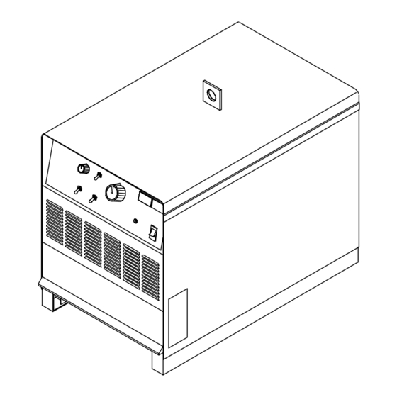
SECTION 5 − OPERATION 5-1. Controls (Non CE And CE Models) Ref. 230 863-A / Ref. 230 864-A Arc Force (Dig) Control Amperage/Voltage Adjustment Control Remote Amperage/Voltage Control Switch When Process Selector switch is in the Control increases SMAW short-circuit Constant Current position, turn control •... -
Page 34: Section 6 − Maintenance & Troubleshooting
SECTION 6 − MAINTENANCE & TROUBLESHOOTING 6-1. Routine Maintenance Disconnect and lockout/tagout input power before per- forming maintenance or troubleshooting procedures. n = Check Z = Change ~ = Clean l = Replace * To be done by Factory Authorized Service Agent Every Months l Unreadable Labels... -
Page 35: Troubleshooting
6-4. Troubleshooting Trouble Remedy No weld output; unit completely Place line disconnect device in On position (see Section 4-17). inoperative; pilot light PL1 off. Check for open line fuse(s), and replace if open (see Section 4-17). Check for proper input power connections (see Section 4-17). Check for proper jumper link position (see Section 4-16). -
Page 36: Section 7 − Electrical Diagram
SECTION 7 − ELECTRICAL DIAGRAM Figure 7-1. Circuit Diagram OM-228 470 Page 32... - Page 37 228 467-B OM-228 470 Page 33...
-
Page 38: Section 8 − Parts List
SECTION 8 − PARTS LIST Hardware is common and not available unless listed. 804 628--A Figure 8-1. Main Assembly (652 Model Illustrated) OM-228 470 Page 34... - Page 39 Item Dia. Part Mkgs. Description Quantity Figure 8-1. Main Assembly (652 Model Illustrated) ..... +179 432 PANEL, side ..........
- Page 40 ... Hardware is common and not available unless listed. 15 12 804 613-A Figure 8-2. Panel, Front w/Components (Fig 8-1 Item 30) Item Dia. Part Mkgs. Description Quantity Figure 8-2. Panel, Front w/Components (Fig 8-1 Item 28) .
- Page 41 Item Dia. Part Mkgs. Description Quantity Figure 8-2. Panel, Front w/Components (Fig 8-1 Item 28) (Continued) ..R4, R5 ..136 076 RESISTOR, ww fxd 30 w 200 ohm faston term .
- Page 42 Item Dia. Part Mkgs. Description Quantity Figure 8-3. Rectifier, Si Diode (Fig 8-1 Item 29) ..C7.12 ..048 420 CAPACITOR, cer disc .01uf 1000VDC ......
- Page 43 Item Dia. Part Mkgs. Description Quantity Figure 8-4. Panel, Rear w/Components (Fig 8-1 Item 18) ....173 283 CHAMBER, plenum 14 in ........
- Page 44 Notes...
- Page 45 Notes...
- Page 46 Notes...
- Page 47 Effective January 1, 2007 (Equipment with a serial number preface of “LH” or newer) This limited warranty supersedes all previous Miller warranties and is exclusive with no other Warranty Questions? guarantees or warranties expressed or implied. LIMITED WARRANTY − Subject to the terms and conditions...
-
Page 48: Options And Accessories
Contact the Delivering Carrier to: File a claim for loss or damage during shipment. For assistance in filing or settling claims, contact your distributor and/or equipment manufacturer’s Transportation Department. © PRINTED IN USA 2007 Miller Electric Mfg. Co. 2007−01...
Need help?
Do you have a question about the Dimension Subarc 652 and is the answer not in the manual?
Questions and answers