
Related Manuals for Miller Spectrum 875 Auto-Line


Summary of Contents for Miller Spectrum 875 Auto-Line
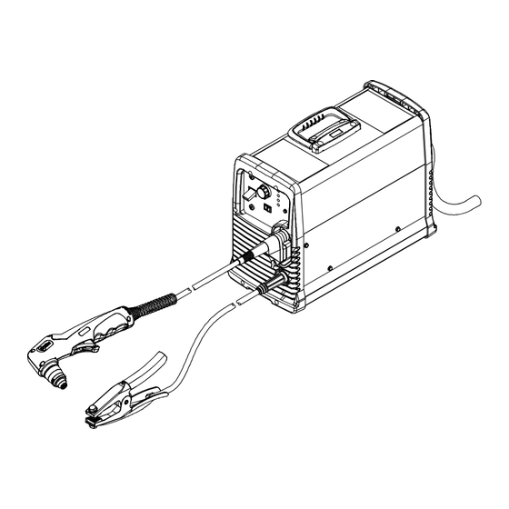
- Page 1 OM-264 260B 2013−09 Processes Air Plasma Cutting and Gouging Description Air Plasma Cutter Spectrum 875 Auto-Line And XT60 Torch File: Plasma Cutters Visit our website at www.MillerWelds.com...
- Page 2 We know you don’t have time to do it any other way. That’s why when Niels Miller first started building arc welders in 1929, he made sure his products offered long-lasting value and superior quality.
-
Page 3: Table Of Contents
............5-9. Wiring Optional 240 Volt Plug (119 172) For Connection To Miller Bobcat, Trailblazer Or Hobart Champion 10,000 . - Page 4 TABLE OF CONTENTS SECTION 7 − MECHANIZED OPERATION ........... . . 7-1.
-
Page 5: Section 1 − Safety Precautions - Read Before Using
SECTION 1 − SAFETY PRECAUTIONS - READ BEFORE USING pom_2011-10 Protect yourself and others from injury — read, follow, and save these important safety precautions and operating instructions. 1-1. Symbol Usage DANGER! − Indicates a hazardous situation which, if Indicates special instructions. not avoided, will result in death or serious injury. -
Page 6: Electric Shock Can Kill
FUMES AND GASES can be hazardous ELECTRIC SHOCK can kill. SIGNIFICANT DC VOLTAGE exists in Cutting produces fumes and gases. Breathing inverter power sources AFTER the re- these fumes and gases can be hazardous to your health. moval of input power. Keep your head out of the fumes. -
Page 7: Additional Symbols For Installation, Operation, And Maintenance
1-3. Additional Symbols For Installation, Operation, And Maintenance HOT PARTS can burn. FALLING EQUIPMENT can injure. D Do not touch hot parts bare handed. D Use lifting eye to lift unit only, NOT running gear, gas cylinders, or any other accessories. D Allow cooling period before working on equipment. -
Page 8: California Proposition 65 Warnings
1-4. California Proposition 65 Warnings Welding or cutting equipment produces fumes or gases This product contains chemicals, including lead, known to which contain chemicals known to the State of California to the state of California to cause cancer, birth defects, or other cause birth defects and, in some cases, cancer. -
Page 9: Section 2 − Consignes De Sécurité − Lire Avant Utilisation
SECTION 2 − CONSIGNES DE SÉCURITÉ − LIRE AVANT UTILISATION pom_2011−10fre Pour écarter les risques de blessure pour vous−même et pour autrui — lire, appliquer et ranger en lieu sûr ces consignes relatives aux précautions de sécurité et au mode opératoire. 2-1. - Page 10 D Coupez l’alimentation d’entrée avant d’installer l’appareil ou d’ef- ÉTINCELLES PROJETÉES fectuer l’entretien. Verrouillez ou étiquetez la sortie d’alimentation peuvent provoquer des blessures. selon la norme OSHA 29 CFR 1910.147 (reportez−vous aux Prin- cipales normes de sécurité). Le coupage plasma produit des étincelles et projec- tions de métal à...
-
Page 11: Dangers Supplémentaires En Relation Avec L'installation, Le Fonctionnement Et La Maintenance
D Si vous êtes à l’intérieur au moment du coupage, ventilez la pièce D Ne pointez pas le chalumeau en direction de votre corps ni de la ou ayez recours à une ventilation aspirante installée près de l’arc pièce à couper lorsque vous appuyez sur la gâchette − l’arc pilote pour évacuer les vapeurs et les gaz. - Page 12 Risque D’INCENDIE OU LIRE LES INSTRUCTIONS. D’EXPLOSION. D Lire et appliquer les instructions sur les étiquettes et le Mode d’emploi avant l’instal- D Ne pas placer l’appareil sur, au-dessus ou à lation, l’utilisation ou l’entretien de l’appareil. proximité de surfaces infllammables. Lire les informations de sécurité...
-
Page 13: Proposition Californienne 65 Avertissements
2-4. Proposition californienne 65 Avertissements Les équipements de soudage et de coupage produisent des Ce produit contient des éléments chimiques, dont le plomb, fumées et des gaz qui contiennent des produits chimiques reconnus par l’État de Californie pour leur caractère dont l’État de Californie reconnaît qu’ils provoquent des mal- cancérogène ainsi que provoquant des malformations formations congénitales et, dans certains cas, des cancers. -
Page 14: Section 3 − Definitions
SECTION 3 − DEFINITIONS 3-1. Additional Safety Symbols And Definitions Some symbols are found only on CE products. Warning! Watch Out! There are possible hazards as shown by the symbols. Safe1 2012−05 When power is applied failed parts can explode or cause other parts to explode. Safe26 2012−05 3-2. -
Page 15: Section 4 − Specifications
A complete Parts List is available at www.MillerWelds.com SECTION 4 − SPECIFICATIONS 4-1. Serial Number And Rating Label Location The serial number and rating information for this product is located on the bottom. Use rating label to determine input power requirements and/or rated output. -
Page 16: Duty Cycle And Overheating
A complete Parts List is available at www.MillerWelds.com General −− −− Toppling or tilting Up to 15 incline −− −− Gas Type Air or Nitrogen Clean, moisture−free, −− −− Gas Quality oil−free 90 PSI (621 kPa) 120 PSI (827 kPa) Gas Inlet Flow and Pressure 6.5 SCFM (184 L/min) −−... -
Page 17: Torch Dimensions
A complete Parts List is available at www.MillerWelds.com 4-4. Torch Dimensions Hand-Held Torch 8-3/4 in. (222 mm) 1-1/2 in. (38 mm) 1-3/16 in. (30 mm) Machine Torch 15-19/32 in. (396 mm) long body 6-19/32 in. (168 mm) short body 2-9/64 in. (54 mm) 1-1/16 in. -
Page 18: Section 5 − Installation
A complete Parts List is available at www.MillerWelds.com SECTION 5 − INSTALLATION 5-1. Selecting a Location Lifting Handle Use handle to lift unit. Line Disconnect Device Do not move or operate Locate unit near correct input unit where it could tip. power supply. -
Page 19: Connecting Work Clamp And Gas/Air Supply
A complete Parts List is available at www.MillerWelds.com 5-2. Connecting Work Clamp and Gas/Air Supply Work Clamp Workpiece Connect work clamp to portion of workpiece that does not fall away after being cut. Connect work clamp to a clean, paint-free location on workpiece, as close to cutting area as possible. -
Page 20: Connecting And Disconnecting Torch
A complete Parts List is available at www.MillerWelds.com 5-3. Connecting And Disconnecting Torch Turn off power source and disconnect input power. Torch Connector Quick Connect Collar Nipple Receptacle Securing Pin To connect torch: Push torch connector onto receptacle and quick connect until collar secures nipple. -
Page 21: Electrical Service Guide
A complete Parts List is available at www.MillerWelds.com 5-5. Electrical Service Guide Elec Serv 2011−08 Failure to follow these electrical service guide recommendations could create an electric shock or fire hazard. These recommenda- tions are for a dedicated circuit sized for the rated output and duty cycle of the welding power source. In dedicated circuit installations, the National Electrical Code (NEC) allows the receptacle or conductor rating to be less than the rating of the circuit protection device. -
Page 22: Extension Cord Data
A complete Parts List is available at www.MillerWelds.com 5-6. Extension Cord Data When calculating max. cord length, remember to include conductor length from line disconnect device to input power receptacle. Input Power Fuse Size Or Input Voltage Phase Hertz Circuit Breaker Rating Conductor Size Max. - Page 23 A complete Parts List is available at www.MillerWelds.com Notes OM-264 260 Page 19...
-
Page 24: Connecting 1-Phase Input Power
A complete Parts List is available at www.MillerWelds.com 5-7. Connecting 1-Phase Input Power =GND/PE Earth Ground Tools Needed: input1 2012−05 − 803 766-C / 805 159 OM-264 260 Page 20... - Page 25 A complete Parts List is available at www.MillerWelds.com 5-7. Connecting 1-Phase Input Power (Continued) connected to any input power between 208 Disconnect Device (switch shown in the Installation must meet all National and and 230 VAC without removing cover to relink OFF position) Local Codes −...
-
Page 26: Connecting 3-Phase Input Power
A complete Parts List is available at www.MillerWelds.com 5-8. Connecting 3-Phase Input Power = GND/PE Earth Ground Tools Needed: input2 2012−05 − 803 766-C / 805 159 OM-264 260 Page 22... - Page 27 A complete Parts List is available at www.MillerWelds.com 5-8. Connecting 3-Phase Input Power (Continued) voltage available at site. This unit can be Input Conductors (L1, L2 And L3) Installation must meet all National and connected to any input power between 208 Local Codes −...
-
Page 28: Wiring Optional 240 Volt Plug (119 172) For Connection To Miller Bobcat
A complete Parts List is available at www.MillerWelds.com 5-9. Wiring Optional 240 Volt Plug (119 172) For Connection To Miller Bobcat, Trailblazer Or Hobart Champion 10,000 Check input voltage available at the power supply. The Auto-LineE circuitry in this unit automatically adapts the... -
Page 29: Connecting To Miller Welder/Generator With A Three-Phase Ac Power Plant
A complete Parts List is available at www.MillerWelds.com 5-10. Connecting To Miller Welder/Generator With A Three-Phase AC Power Plant Three-Phase Generator Power Stop engine. Power and weld outputs are live at the same time. Discon- Three-Phase Power Connection nect insulate unused cables. -
Page 30: Generator Settings For Plasma Cutter Operation
A complete Parts List is available at www.MillerWelds.com 5-11. Generator Settings For Plasma Cutter Operation Engine Control Switch must be set at Set generator Fine Adjustment Control to 10 “RUN” position − not “RUN/IDLE”. for maximum auxiliary power, if applicable. The peak kW at arc stretch of this plasma power source is 15.5 kW. -
Page 31: Section 6 − Operation
A complete Parts List is available at www.MillerWelds.com SECTION 6 − OPERATION 6-1. Controls Ref. 234 155-A Output Control Cut/Gouge Switch Use only clean, dry air with 90 to 120 psi Use control to set cutting output. Place switch in appropriate position for de- (621 to 827 kPa) pressure. -
Page 32: Trigger Safety Lock
A complete Parts List is available at www.MillerWelds.com 6-2. Trigger Safety Lock Trigger Trigger Locked Trigger Unlocked Ref. 253 554-A 6-3. Plasma Cutting System Practices The pilot arc starts immediately when trigger is pressed. GOUGE Always connect work clamp to a clean, DO NOT start pilot arc without cutting or Set switch to either cut or gouge paint-free location on workpiece, as close to... -
Page 33: Sequence Of Cutting Operation
A complete Parts List is available at www.MillerWelds.com 6-4. Sequence Of Cutting Operation GOUGE Connect work clamp to a clean, paint-free Unit automatically regulates pressure to 75 psi location on workpiece, as close to cutting (517 kPa) for cutting. area as possible. Connect work clamp to portion of workpiece that does not fall away after being cut. -
Page 34: Sequence Of Gouging Operation
A complete Parts List is available at www.MillerWelds.com 6-5. Sequence Of Gouging Operation GOUGE Unit automatically regulates pressure Trigger pilot arc once before starting to gouge. to 60 psi (413 kPa) for gouging. Connect work clamp to a clean, paint-free location on workpiece, as close to cutting area as possible. -
Page 35: Sequence Of Piercing Operation
A complete Parts List is available at www.MillerWelds.com 6-6. Sequence Of Piercing Operation The pilot arc starts immediately when trigger is pressed. Recommended maximum piercing capacity is 7/16 in (11 mm). GOUGE Unit automatically regulates pressure to 75 psi (517 kPa) for cutting. Connect work clamp to a clean, paint-free location on workpiece, as Hold torch at approximately 45... -
Page 36: Cutting Speed
A complete Parts List is available at www.MillerWelds.com 6-7. Cutting Speed Mild Steel Material Thickness Recommended Cut Speeds Arc Current Inches mm/min 18ga (0.05) 11,557 16ga (0.06) 11,125 14ga (0.08) 6,985 1/8 (0.13) 2,311 3/16 (0.19) 1,549 1/4 (0.25) 1/4 (0.25) 2.667 3/8 (0.38) 1,372... -
Page 37: Consumables Storage Compartment
A complete Parts List is available at www.MillerWelds.com 6-8. Consumables Storage Compartment Consumables Storage Compartment This compartment provides convenient access to consumables and parts. Rear of Unit Ref. 805 160-A SECTION 7 − MECHANIZED OPERATION 7-1. XT60M Mounting Position XT60M Machine Torch Square Use a square to align torch perpen- dicular to the work surface. -
Page 38: Remote Control Receptacle
(RMT1) or hot [RMT2 (+24 volts dc)] depending on plug position at RMT1 or Okay To Move RMT2 receptacle on Control board PC1. NOTE: The Spectrum 875 Auto-Line with factory-installed machine torch is Green shipped from the factory with the plug connected to RMT1 (dry contacts). To power a relay or isolated input module with +24 volts DC on black lead (socket 2) and circuit common on green lead (socket 4), see Section 7-4 or 7-5. -
Page 39: Volts Dc Hot Contacts For Relay Operation
A complete Parts List is available at www.MillerWelds.com 7-4. +24 Volts DC Hot Contacts For Relay Operation Turn off power source and disconnect input power. Remove wrapper (see Section 8-4). Control board PC1 can supply +24 volts DC from receptacle RMT2 to operate a customer-supplied relay for the Okay To Move signal. -
Page 40: Volts Dc Hot Contacts For Isolated Input Module Operation
A complete Parts List is available at www.MillerWelds.com 7-5. +24 Volts DC Hot Contacts For Isolated Input Module Operation Turn off power source and disconnect input power. Remove wrapper (see Section 8-4). Control board PC1 can supply +24 volts DC from receptacle RMT2 to operate customer-supplied isolated input module for the Okay... -
Page 41: Dry Contacts Using An External Power Supply For Relay Operation
A complete Parts List is available at www.MillerWelds.com 7-6. Dry Contacts Using An External Power Supply For Relay Operation Turn off power source and disconnect input power. Remove wrapper (see Section 8-4). Control board PC1 can provide dry contacts from receptacle RMT1 to operate a customer-supplied relay using an external power supply for the Okay To Move signal. -
Page 42: Dry Contacts Using An External Power Supply For Isolated Input Module Operation
A complete Parts List is available at www.MillerWelds.com 7-7. Dry Contacts Using An External Power Supply For Isolated Input Module Operation Turn off power source and disconnect input power. Remove wrapper (see Section 8-4). Control board PC1 can provide dry contacts from receptacle RMT1 to operate customer-supplied... -
Page 43: Remote Voltage Sense Connection
A complete Parts List is available at www.MillerWelds.com 7-8. Remote Voltage Sense Connection Turn off power source and disconnect input power. Remove wrapper (see Section 8-4). Remote voltage sense is an arc voltage output signal for automatic torch height adjustment. Snap-in Blank Secondary Interconnect Board PC4... -
Page 44: Cut Charts
A complete Parts List is available at www.MillerWelds.com 7-10. Cut Charts 60 Amp Machine Torch Shielded Consumables The following cut charts are based on a distance of 1/16 in. (1.5 mm) between torch and workpiece for all cuts. Shield Retaining Cap Electrode Swirl Ring O−Ring... - Page 45 A complete Parts List is available at www.MillerWelds.com Stainless Material Thickness Maximum Cut Speeds Optimum Cut Speeds Pierce Arc Current Arc Voltage Delay Inches mm/min mm/min 26 Ga 16027 10414 22 Ga 12598 8179 18 Ga 15037 8509 16 Ga 9500 6172 0.25...
-
Page 46: Section 8 − Maintenance & Troubleshooting
A complete Parts List is available at www.MillerWelds.com SECTION 8 − MAINTENANCE & TROUBLESHOOTING 8-1. Routine Maintenance Maintain more often Disconnect power during severe conditions. before maintaining. n = Check Z = Change ~ = Clean l = Replace Reference * To be done by Factory Authorized Service Agent Each n Torch Tip, Electrode,... -
Page 47: Checking/Replacing Retaining Cup, Tip, And Electrode
A complete Parts List is available at www.MillerWelds.com 8-3. Checking/Replacing Retaining Cup, Tip, And Electrode Overtightening will strip threads. Do not overtighten retaining cup during assembly. Do not cross-thread parts causing stripping. Use care during torch assembly and parts replacement. Inspect shield cup, tip, and electrode for wear before cutting or whenever cutting speed has been signifi- cantly reduced. -
Page 48: Wrapper Removal/Installation
A complete Parts List is available at www.MillerWelds.com 8-4. Wrapper Removal/Installation Turn power, disconnect input power plug from receptacle or turn off and lockout/tagout line dis- connect device before working on unit. Significant DC voltage can remain on capacitors after unit is Off. -
Page 49: Checking Or Replacing Filter Element (Part No. 227 877)
A complete Parts List is available at www.MillerWelds.com 8-5. Checking Or Replacing Filter Element (Part No. 227 877) Turn power, disconnect input power plug from receptacle or turn off and lockout/tagout line dis- connect device before working on unit. Significant DC voltage can remain on capacitors after unit is Off. -
Page 50: Status/Trouble Lights
A complete Parts List is available at www.MillerWelds.com 8-6. Status/Trouble Lights Light Condition Status/Possible Cause Power Input power is okay. When Power light is on, system is normal if these lights Pressure/Cup/T emp are off. Flashing rate is steady for 15 seconds or until torch trigger Input power was above 300 volts AC or below 156 volts Power is pressed again, whichever comes first. -
Page 51: Troubleshooting Power Source
A complete Parts List is available at www.MillerWelds.com 8-7. Troubleshooting Power Source Trouble Remedy No pilot arc; difficulty in establishing an Clean or replace worn consumables as necessary (see Section 8-3). arc. Check for damaged torch or torch cable. Check position of cut/gouge switch. If using cutting consumables, be sure that switch is in the CUT position. -
Page 52: Troubleshooting Torch
A complete Parts List is available at www.MillerWelds.com Trouble Remedy Cup status light flashes steady for 15 System failed to strike an arc. Power source failed to deliver current to the output. Check continuity of seconds or until torch trigger is pressed, torch connections (pilot lead and electrode lead). - Page 53 Notes OM-264 260 Page 49...
-
Page 54: Section 9 − Electrical Diagram
SECTION 9 − ELECTRICAL DIAGRAM Figure 9-1. Circuit Diagram OM-264 260 Page 50... - Page 55 243 018-C OM-264 260 Page 51...
-
Page 56: Section 10 − Parts List
SECTION 10 − PARTS LIST A complete Parts List is available on-line at www.MillerWelds.com 10-1. Recommended Spare Parts Item Dia. Part Mkgs. Description Quantity Recommended Spare Parts ....265172 Label, XT60 Consumables . - Page 57 Item Part Description 263 950 Torch Handle Kit (1) 249 971 Torch Trigger ....Microswitch (1) 249 961 Leads, 20 ft (1) 249 962 Leads, 50 ft (1) 256 039 Torch Body Kit (1) 249 972...
- Page 58 See Figure 10-1 for Item Part additional consumable parts. Description 259 357 Long Body Positioning Sleeve (1) 263 389 Short Body Positioning Sleeve (1) 249 963 Torch Lead, Replacement W/QD 25 ft (1) 249 962 Torch Lead, Replacement W/QD 50 ft (1) 259 361 Torch Sleeve (1) 256 040...
- Page 59 Effective January 1, 2013 (Equipment with a serial number preface of MD or newer) This limited warranty supersedes all previous Miller warranties and is exclusive with no other guarantees or warranties expressed or implied. Warranty Questions? LIMITED WARRANTY − Subject to the terms and conditions below, 6 Months —...
- Page 60 Contact the Delivering Carrier to: File a claim for loss or damage during shipment. For assistance in filing or settling claims, contact your distributor and/or equipment manufacturer’s Transportation Department. ORIGINAL INSTRUCTIONS − PRINTED IN USA 2013 Miller Electric Mfg. Co. 2013−01...
Need help?
Do you have a question about the Spectrum 875 Auto-Line and is the answer not in the manual?
Questions and answers