
Subscribe to Our Youtube Channel
Related Manuals for Delta SOLIVIA 10 EU T4 TL


Summary of Contents for Delta SOLIVIA 10 EU T4 TL
- Page 1 Operation and Installation manual SOLIVIA 10 EU T4 TL SOLIVIA 15 EU G4 TL SOLIVIA 20 EU G4 TL SOLIVIA 30 EU T4 TL PRELIMINARY...
- Page 3 The technical instructions and illustrations contained in this manual are to be treated as confidential and no part may be repro- duced without the prior written permission of Delta Energy Systems Service engineers and end users may not divulge the informa- tion contained herein or use this manual for purposes other than those strictly connected with correct use of the equipment.
-
Page 4: Table Of Contents
Table of Contents 1. General Safety Instructions ......11 2. General Information....... 24 About this Manual . - Page 5 6.2.4 AC Wiring Considerations ......54 DC Connection (from PV array) ..... 54 6.3.1 Asymmetrical Loading for 10 TL, 15 TL, 20 TL, and 30 TL .
- Page 6 7.3.6.4.4 cosφ(P) ..........89 7.3.6.4.5 Constant Reactive Power.
- Page 7 Figures Figure 2.1.: Solar Inverter System Operation Illustration ... . . 26 Figure 3.1.: Unpacking Process ......29 Figure 3.2.: The Type Label 10 TL and 15 TL .
- Page 8 Figure 6.13.: SOLIVIA 20 TL Efficiency Curve ....59 Figure 6.14.: SOLIVIA 30 TL Efficiency Curve ....60 Figure 6.15.: Communication module removal .
- Page 9 Figure 7.31.: cosφ(P) graph ......90 Figure 7.32.: cos φ(P) settings page ......91 Figure 7.33.: Constant Reactive Power settings page .
- Page 10 Tables Table 3.1.: Packing List ......28 Table 6.1.: Cable cross sections and torques for AC connectors ..48 Table 6.2.: Permitted earthing systems .
-
Page 11: General Safety Instructions
For this reason, observe and follow all general safety instructions and warnings. ● The solar inverter contains no components that must be maintained or repaired by the opera- tor or installer. All repairs must be performed by Delta Energy Systems. Opening the cover will void the warranty. ●... - Page 12 ● Der Solar Wechselrichter kann nur sicher und normal betrieben werden, wenn Installation und Betrieb nach Maßgabe dieses Handbuchs erfolgen (siehe IEC 62109-5.3.3). Delta En- ergy Systems ist für Schäden, die durch Nicht-Einhaltung der Installations- und Betriebsan- weisungen in diesem Handbuch entstehen, nicht verantwortlich. Beachten und befolgen Sie...
- Page 13 Sicherheitshinweise und handlungsbezogenen Warnhinweise. ● Der Solar Wechselrichter enthält keine Komponenten, die vom Bediener oder Installateur zu warten oder zu reparieren sind. Sämtliche Reparaturen müssen von Delta Energy Systems durchgeführt werden. Durch Öffnen der Abdeckung erlischt die Garantie. ●...
- Page 14 ● Per garantirne il funzionamento normale e sicuro, installare e usare l’inverter attenendosi alle condizioni e misure indicate nel presente manuale (vedi IEC 62109-5.3.3). Delta Energy Sys- tems declina ogni responsabilità per eventuali danni derivati dall’inosservanza delle istruzioni per l’installazione e l’uso contenute nel presente manuale. Attenersi perciò scrupolosamente a tutte le istruzioni riportate nel presente manuale! ●...
- Page 15 L’onduleur photovoltaïque ne peut fonctionner normalement et correctement que si son ins- tallation et son exploitation ont lieu conformément au présent manuel (voir CEI 62109-5.3.3). Delta Energy Systems ne saurait être tenu pour responsable des dommages causés par le non-respect des consignes d’installation et de fonctionnement mentionnées dans le présent manuel.
- Page 16 ● L’onduleur photovoltaïque ne contient pas de composants qui doivent être entretenus ou ré- parés par l’utilisateur ou l’installateur. Toutes les réparations doivent être réalisées par Delta Energy Systems. L’ouverture du couvercle entraîne l’annulation de la garantie. ●...
- Page 17 (véase la norma IEC 62109-5.3.3). Delta Energy Systems no se responsabiliza por los daños derivados del incumplimiento de las instrucciones de servicio e instalación contenidas en el presente manual.
- Page 18 De omvormer voor zonne-energie kan alleen veilig en normaal worden gebruikt wanneer de installatie en het gebruik volgens dit handboek plaatsvinden (zie IEC 62109-5.3.3). Delta Energy Systems is niet verantwoordelijk voor schade die ontstaat door het niet in acht nemen van de installatie- en gebruiksvoorschriften in dit handboek.
- Page 19 ● De omvormer voor zonne-energie bevat geen componenten die door de gebruiker of installa- teur onderhouden of gerepareerd moeten worden. Alle reparaties moeten door Delta Energy Systems worden uitgevoerd. Indien de afdekking wordt geopend, vervalt de garantie. ●...
- Page 20 ● Solcelleinverteren indeholder ingen komponenter, der skal vedligeholdes eller repareres af brugeren eller montøren. Samtlige reparationer skal udføres af Delta Energy Systems. Garantien ophører, hvis dækslet åbnes. ● Træk ikke kablerne ud, mens solcelleinverteren er tilsluttet strømmen, da der er fare for lysbuefejl.
- Page 21 ● Solárny invertor neobsahuje žiadne komponenty, na ktorých by obsluha alebo inštalatéri museli vykonávať údržbu alebo opravy. Všetky opravy musia vykonávať pracovníci z Delta Energy Systems. Otvorením krytu zaniká záruka. ●...
- Page 22 ● Solární střídač lze bezpečně a normálně provozovat jen tehdy, když jeho instalaci a provoz provedete v souladu s touto příručkou (viz IEC 62109-5.3.3). Společnost Delta Energy Systems nezodpovídá za škody, ke kterým dojde v důsledku nedodržení instalačních a provozních pokynů uvedených v této příručce. Proto dbejte všech pokynů v této příručce a dodržujte je!
- Page 23 General Safety Instructions Delta Energy Systems. Otevřením krytu ztrácíte nárok na plnění ze záruky. ● Kabely neodpojujte, dokud je solární střídač pod zatížením, protože hrozí nebezpečí rušivého světelného oblouku. ● Zajistěte prevenci proti zásahu bleskem, a to dodržováním ustanovení platných ve vaší zemi.
-
Page 24: General Information
Please do not touch! Validity This user manual describes the installation procedures, maintenance, technical data and safety instruction of the following solar inverter models under the DELTA brand. Model Software:: DSP ver. Red. ver. -
Page 25: Product Description
General Information Product Description The SOLIVIA 10 TL / 15 TL / 20 TL / 30 TL are 3 phase grid-tied solar inverters with reactive power control. These devices convert direct current (DC) electricity from photovoltaic power collected from PV arrays into 3 phase alternating current (AC) to feed the excess capacity back to the local mains electrical grid. -
Page 26: Additional Information
*Please note at the time of printing, all countries shown may not necessarily be available for 30 TL model, but are expected to be completed within Q1 2013. Please check with the Delta support team for questions about countries approved. -
Page 27: Monitoring
The 10 TL, 15 TL, 20 TL, and 30 TL with Solar Log and Meteocontrol as well as Delta’s own monitoring solution, SOLIVIA Monitor G2. Please contact your Delta supplier for more information on these remote monitoring options. -
Page 28: Preparing For Installation
Preparing for Installation Preparing for Installation Instruction before Installing Due to the variety of user installation environments, reading the manual thoroughly before installa- tion is strongly recommended. All the installation and start-up procedures must be undertaken by a professional and well-trained technician. Checking the Package There might be some unpredictable situations during transportation. -
Page 29: Unpacking
Preparing for Installation Unpacking Open the top of the cardboard box as shown in the figure below. Remove the top packing material after opening the box. Lift the Inverter out of the package and save the packaging in case of return. Figure 3.1.: Unpacking Process... -
Page 30: Identify The Inverter
Preparing for Installation Identify the Inverter User can identify the model number by the information on the product label. The model number, specification as well as the series no. is specified on the product label. In regard to the label loca- tion, please refer to the below figure. -
Page 31: Product Overview
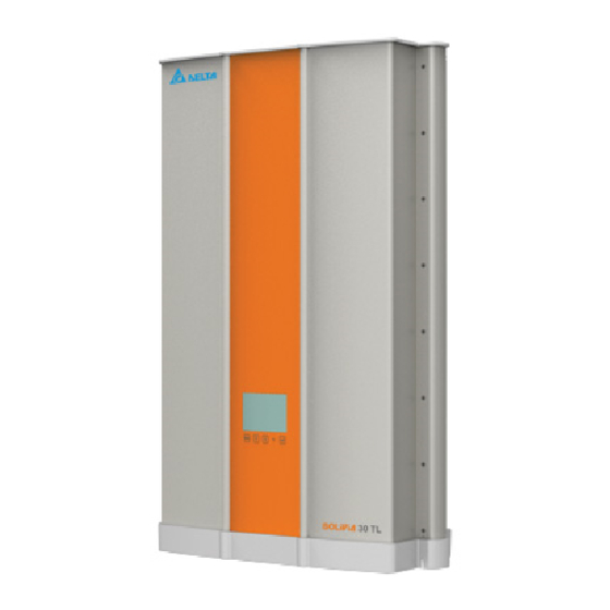
Product Overview Product Overview Dimensions SOLIVIa 10 TL Top view 625 [24.6] 275 [10.83] Front view Side view Rear view Bottom view Figure 4.1.: Dimensions of SOLIVIA 10 TL... -
Page 32: Dimensions Solivia 15 Tl, 20 Tl, 30 Tl
Product Overview Dimensions SOLIVIa 15 TL, 20 TL, 30 TL Top view 275 [10.83] 625 [24.6] Side view Rear view Front view Bottom view: 15 TL / 20 TL Bottom view: 30 TL Figure 4.2.: Dimensions of SOLIVIA 15 TL / 20 TL / 30 TL... -
Page 33: Function Introduction
Product Overview Function Introduction Inverter exterior features are shown on figure 4.3 and 4.4, and a more detailed description is found in the sections from 4.3.1 to 4.3.3 Air outlets LCD/LED Display Buttons AC Connector *Note: The fan is shown without the required protective screen for illustrative purposes Communication... -
Page 34: Figure 4.4.: 15 Tl / 20 Tl / 30 Tl Inverter Exterior View
Product Overview Air outlets LCD/LED Display Buttons *Note: The fans shown are without the required protective screen for illustrative purposes AC Connector Please note the 15 TL / 20 TL model Communication is shown here. The 30 TL will look Connections slightly different - a different AC connector and 2 addl. -
Page 35: Lcd Display And Buttons
Product Overview The chassis has a predrilled hole to accept a grounding screw as shown. The maximum torque ➀ of the M6 grounding screw is 4.4 Nm. There is a 15 mm diameter unpainted surface around the center of the ground screw hole that allows for a solid ground connection when installing the grounding kit. -
Page 36: Inverter Input/Output Interface
Product Overview 4.3.2 Inverter Input/Output Interface DC input panel for the 10 ➀ ➁ ➂ TL, 15 TL, and 20 TL has 4 DC inputs. The 30 TL DC input interface shown below, provides 6 DC inputs. SOLIVIA 30 EUT4TL ➃... -
Page 37: Air Outlet
There are 4 fans in the bottom section of the inverter and all fans work synchronously. If any one fan locks up or is defective, it will cause a fan failure and power derating. If you suspect that there is a problem with a fan please call the Delta support hotline. Figure 4.9.: Fan Control 10 TL... -
Page 38: Figure 4.10.: Fan Control 15 Tl And 20 Tl
Product Overview Figure 4.10.: Fan Control 15 TL and 20 TL Figure 4.11.: Fan Control 30 TL... -
Page 39: Installation
Installation Installation Installing Location The SOLIVIA TL inverters can be installed indoors and in protected outdoor areas due to its enclo- sure protection classes IP65 and IP55. See the figure 5.1 for further explanation of the protection classes. WarnInG Death and serious injury may occur if the following instructions are not carefully followed ►... -
Page 40: Mounting
Installation IP65 protection class IP55 protection class Note: 15 and 20 TL pictured. 10 TL and 30 TL may look slightly different. Figure 5.1.: SOLIVIA 10 TL, 15 TL, 20 TL, 30 TL protection classes nOTE The fans shown are without the required protective screen for illustrative purposes. -
Page 41: Figure 5.2.: Attaching The Mounting Bracket To The Wall
Installation SOLIVIA 10 TL rear view Wall SOLIVIA 15 TL, 20 TL, 30 TL rear view 6 pcs. screws 6 pcs. screws Unit: mm Note: The wall mount bracket will be the same part for the 10 TL / 15 TL / 20 TL / 30 TL. Figure 5.2.: Attaching the mounting bracket to the wall... -
Page 42: Figure 5.3.: Correct And Incorrect Installation Illustration
Machine and equipment damage may occur. ► Please leave an appropriate gap in between when installing single / several DELTA solar inverter systems. ► Please install solar inverters at eye level to allow easy observation for operation and parameter setting. -
Page 43: Ambient Temperature
Installation Figure 5.4.: Proper Installation Gap ambient temperature The solar inverter can be operated in an ambient temperature between -20 °C ... +60 °C. The fol- lowing diagram illustrates how the power supplied by the solar inverter is reduced automatically in accordance with the ambient temperature. -
Page 44: Figure 5.5.: Derating Curve For 10 Tl, 15 Tl, 20 Tl And 30 Tl
Installation Pout_max (kVA) 15 kVA / 20 kVA Ambient Temperature ( ℃ ) -20 -15 Figure 5.5.: Derating curve for 10 TL, 15 TL, 20 TL and 30 TL... -
Page 45: Wiring The Inverter
Wiring the Inverter Wiring the Inverter Preparation before Wiring To avoid accidents, please confirm that the PV inverter’s power of both DC and AC are switched off. Please confirm whether the input/output of PV inverter’s wiring are clearly indicated. Make sure that the value, polarity, voltage and phase are correct. -
Page 46: Figure 6.1.: Connection Of System If Dc Inputs Are Floating
Wiring the Inverter PV Array DC Distribution DC Wiring Parallel or Separate Wiring Communication Wiring Figure 6.1.: Connection of system if DC inputs are floating... -
Page 47: Ac Grid Connection: 3 Phase + N + Pe
Wiring the Inverter PV Array DC Distribution Box (Plus-GND or Minus-GND) Must be Parallel Connection Must install one transformer per inverter Isolated transformer Utility To Inverter 3Ph, Δ or Y 3Ph, Y 230/400 Vac 230/400 Vac Figure 6.2.: Connection of system with Positive Ground or Negative Ground aC Grid Connection: 3 Phase + n + PE WarnInG Death and serious injury may occur... -
Page 48: Required Protective Devices And Cable Cross-Sections
Therefore faults that would otherwise require the use of a type B residual-current device due to the inverter can be excluded. The integrated all-pole sensitive residual-current monitoring unit (RCMU) results in additional safety. For all above mentioned transformerless inverters from Delta RCDs of the type A can be used. 6.2.1.2... -
Page 49: Ac Bayonet Connectors For 10 Tl, 15 Tl, 20 Tl
Wiring the Inverter AC wiring can be separated into 3-phase (L1, L2, L3), N, and PE. The following earthing configu- rations are allowed. IT is not allowed. Please see the appendix for further explanation of these earthing systems. Tn-S Tn-C Tn-C-S Table 6.2.: Permitted earthing systems nOTE... -
Page 50: Figure 6.4.: Ac Plug Sealing Ring For Ac Connector 10 Tl, 15 Tl, And 20 Tl
Wiring the Inverter This is a rear view of the cable gland. For a cable sheath diameter between 16 mm to 20 mm, please remove the inner sealing ring. Figure 6.4.: AC plug sealing ring for AC connector 10 TL, 15 TL, and 20 TL... -
Page 51: Figure 6.5.: Ac Connector 10 Tl, 15 Tl, And 20 Tl
Wiring the Inverter The female cable connector needs to be wired as shown below. Rotate the connector housing and cable gland to remove them from the coupling ring. Slide the connector housing and cable gland onto the cable. nOTE: rear view of cable To wire the connector refer to placement connector of L1, L2, L3, N and PE shown to the left. -
Page 52: Ac Bayonet Connectors For 30 Tl
Wiring the Inverter CaUTIOn Machine and equipment damage may occur. ► Observe the pin assignment of the AC bayonet connector. An incorrect assignment can result in the unit being destroyed. The Figure 6.5 pin out diagram shows the connections inside the AC connector. nOTE Make sure the line is provided with a strain relief device. -
Page 53: Figure 6.7.: Ac Connector For 30 Tl
Wiring the Inverter ➁ ➂ ➀ The female cable connector needs to be wired as shown below. Rotate the connector housing ➀ and cable gland body ➁ and cable gland cap ➂ to remove them from the coupling ring. ➀ ➂... -
Page 54: Ac Wiring Considerations
In the case of damage or bodily harm resulting from the use of this device in a way contrary to it’s intended purpose or as a result of unauthorized modifications made to the parameters of the inverter, Delta will not be held liable in these situations.. -
Page 55: Figure 6.8.: Input/Output Interface
Wiring the Inverter DC input panel for the 10 ➀ ➁ ➂ TL, 15 TL, and 20 TL has 4 DC inputs. The 30 TL DC input interface shown below, provides 6 DC inputs. SOLIVIA 30 EUT4TL ➃ Figure 6.8.: Input/Output Interface Designation Description AC connector... -
Page 56: Asymmetrical Loading For 10 Tl, 15 Tl, 20 Tl, And 30 Tl
Wiring the Inverter Maximum rating of input power: Type of limit 10 TL 15 TL 20 TL 30 TL Total input power 11 kW 16.5 kW 22 kW 30 kW Input 1 & Input 2 7.3 kW 11 kW 14.7 kW 20.1 kW Cable size: Current rating... -
Page 57: Figure 6.10.: Comparison Diagram Of Balanced Power Input And Unbalanced Power Input
Wiring the Inverter Balanced Input Power Max. Current Max. Power MPPT Range Input Current 1 Input Voltage [V] Input Current 2 Unbalanced Input Power 33/67 Max. Current Max. Power MPPT Range Input Current 1 Input Current 2 Input Voltage [V] Figure 6.10.: Comparison diagram of Balanced Power Input and Unbalanced Power Input Maximum rating of input power: Model... -
Page 58: Efficiency
Wiring the Inverter A kit to meet UTE 15712-1 requirements is provided for the SOLIVIA 15 TL and 20 TL and can be ordered from Delta with the part number in the following table. Designation Part number Delta UTE kit Multi-Contact* EOE90000341 *Kit contains caps for 4 strings. -
Page 59: Figure 6.12.: Solivia 15 Tl Efficiency Curve
Wiring the Inverter Efficiency [%] Power 350 V 640 V 800 V Figure 6.12.: SOLIVIA 15 TL Efficiency Curve Efficiency [%] Power 350 V 640 V 800 V Figure 6.13.: SOLIVIA 20 TL Efficiency Curve... -
Page 60: Communication Module Connections
Wiring the Inverter Efficiency [%] Power 350 V 640 V 800 V Figure 6.14.: SOLIVIA 30 TL Efficiency Curve Communication Module Connections The communication module supports the communication functions with a computer, also provides 1 EPO (Emergency Power Off) and 2 sets of dry contacts. The parts of the communication module are shown in Figure 6.15. -
Page 61: Figure 6.15.: Communication Module Removal
Wiring the Inverter 15 TL / 20 TL / 30 TL 10 TL Dry contact Dry contact (Emergency (Emergency Power Off) Power Off) Dip Switch to activate Dip Switch the terminal to activate RS485 resistor RS485 the terminal resistor Figure 6.15.: Communication module removal To remove the communication module follow these instructions: Unscrew and remove the two Phillips screws highlighted above in Figure 6.15. -
Page 62: Rs485 Connection
Wiring the Inverter 6.5.1 rS485 Connection The pin definition of RS485 is shown in Table 6.3. The wiring of multi-inverter connections is shown in Figure 6.16. FUnCTIOn DATA+ DATA- Table 6.3.: Definition of RS485 pin Inverter #1* Inverter #2 Inverter #N *Activate the Terminal Resistor by setting the internal dip switch no. -
Page 63: Epo (Emergency Power Off) Connections
Wiring the Inverter Figure 6.17.: Terminal resistor switch for Multi-inverter Connection To engage the internal Terminal Resistor, place switch number 2 on the communication module in the on position. See figure 6.17 for more information. Baud Rate Programmable, 2400/4800/9600/19200/38400, default = 19200 Data Bit Stop Bit Parity... -
Page 64: Dry Contact Connection
Wiring the Inverter nOTE To shutdown the inverter, short pin 1 and 2 or short pin 4 and 5. 6.5.3 Dry Contact Connection Provides 2 sets of Dry Contact functions - NO1 and NO2. Please refer to Figure 6.16 for connec- tion diagram and read below for more details. -
Page 65: Operating The Pv Inverter
*Please note at the time of printing, all countries shown may not necessarily be available for 30 TL model, but are expected to be completed within Q1 2013. Please check with the Delta support team for questions about countries approved. -
Page 66: Figure 7.1.: Country Settings On Initial Startup
Operating the PV inverter Grid (as shown Description 10 TL 15 TL 20 TL 30 TL on the Display) Australia Australia AS 4777 Belgium Belgium as per C10/11, June 2012 Bulgaria Bulgaria as per VDE 0126 Czech Czech Republic as per VDE 0126 Denmark Denmark as per VDE AR N 4105 France... -
Page 67: Figure 7.2.: Lcd Display And Control Panel
Operating the PV inverter nOTE ► If selecting Germany or Italy as the country, it could be necessary to adjust active and reactive power settings (Information for the settings will come from the local grid operator). ► If needed please call the local support hotline for assistance in setting up Germany MVD/LVD or Italy CEI 0-21/A70 grid settings. -
Page 68: Disconnection Parameter Settings
Operating the PV inverter Inverter Status Green LED red LED Standby or Countdown FLASHING - on 1 sec. and off 1 sec. Power ON Error or Fault Night time (No DC) Bootloader mode FLASHING - on 1 sec. and off 1 sec., first the green LED then the red LED in alternating sequence Table 7.1.: LED indicator Disconnection Parameter Settings... -
Page 69: Spi Device
Operating the PV inverter At any time, while you are viewing one of the 4 grid setting windows, you are able to switch off the power disconnection device by simultaneously pressing the up and down buttons and holding for more than 5 seconds. See the tables below for the LVD/MVD allowed parameter ranges according to the regulations: When the selected grid is LVD, the following adjustable vaules are allowed: Parameter... -
Page 70: Home Page
Operating the PV inverter home Page When the inverter is operating normally, the LCD will show the home page as shown in Figure 7.4. On the home page the user can find the output power, inverter status, E-today, date and time. Today Power Date and Time Today Runtime... -
Page 71: Power Meter
Operating the PV inverter “„7.3.1 Power Meter“ on page 71 “„7.3.2 Statistics“ on page 71 “„7.3.3 Logs“ on page 72 “„7.3.4 Actual data“ on page 73 “„7.3.5 Inverter Information“ on page 74 “„7.3.6 Settings“ on page 74 7.3.1 Power Meter Figure 7.6.: Power Meter Pages 7.3.2 Statistics... -
Page 72: Logs
Operating the PV inverter Figure 7.7.: Statistics Pages 7.3.3 Logs After pressing EnT on this page, the user can view the internal log and can view the events log. 7.3.3.1 Internal Data The internal data shows all messages coming from the inverter. These messages indicate the sta- tus of internal processes and also changes on the AC and DC terminals, for example: frequency, voltage, etc. -
Page 73: Actual Data
Operating the PV inverter Figure 7.9.: Events Journal Flow Chart 7.3.4 actual data Actual data includes 4 pages and records the maximum and/or minimum historical values, includ- ing voltage, current, power and temperature. Figure 7.10.: Actual Data Flow Chart... -
Page 74: Inverter Information
Operating the PV inverter 7.3.5 Inverter Information This page includes the following information: serial number, firmware version, installation date, and inverter ID. To change the inverter ID, please refer to “„7.3.6.2 Install Settings“ on page Figure 7.11.: Inverter Information Page nOTE The information shown in Figure 7.11 is for illustration purposes and may not match the actual information displayed on your inverter. -
Page 75: General Settings
Operating the PV inverter nOTE FRT is only accessible if you have selected Germany MVD, Italy CEI 021 or Italy A70 as your grid selection. 7.3.6.1 General Settings Settings in the General Settings include Language, Date, Time, Screen Saver, Brightness, Con- trast, Baud Rate, CO2 saved, Earning Value, and Currency. -
Page 76: Active/Reactive Power Control For De Lvd And De Mvd
Operating the PV inverter Password is 5555. Figure 7.14.: Install Settings Page - Installer Mode ● Inverter ID: This setting is used to set unique ID‘s for installations with more than one inverter. In a multi-inverter installation where the inverters will be in a network, each inverter must have a unique ID. -
Page 77: Figure 7.16.: Active/Reactive Power Settings Page
Operating the PV inverter Feature available for Description Power limit To reduce the maximum power production Power vs. frequency To set the power gradiant in dependency of the frequency Reactive power control Constant cos φ To set a fixed cos φ (inductive or capacative) cos φ... -
Page 78: Power Limit
Operating the PV inverter CaUTIOn Machine and equipment damage may occur. ► Please only adjust active and reactive power settings if you are a quali- fied electrical technician with the knowledge to do so ► Adjustments may affect energy production ►... -
Page 79: Power Vs. Frequency
Operating the PV inverter available power When Actual Power is 100% output power selected the output power is based on the percentage of the avail- able power (dotted path) If the set point is 75% then B=75% of A. 4:00 8:00 12:00 16:00... -
Page 80: Figure 7.19.: Lvd Curve Power Vs. Frequency
Operating the PV inverter Gradient (%/Hz) Gradient (%/Hz) f start f stop f recovery f start f stop f (Hz) f(Hz) Figure 7.19.: LVD Curve power vs. frequency Figure 7.20.: MVD Curve power vs. frequency nOTE The Power vs Frequency function is required for LVD and MVD. -
Page 81: 7.3.6.3.3 Constant Cos Φ
Operating the PV inverter 7.3.6.3.3 Constant cos φ This feature is available for LVD and MVD grids. This feature allows the user to set up a constant φ. Figure 7.22.: Constant cos φ settings page adjustable parameters Parameter adjustable values Description cos φ inductive | capacitive Sets the cos φ... -
Page 82: Constant Reactive Power
Operating the PV inverter Figure 7.23.: cos φ(P) settings page adjustable parameters Parameter adjustable values Description Upper limit - cos φ Ind 0.80 ... Cap 0.80 The upper limit cos φ must be greater than the lower limit cos φ Lower Power 0 ... -
Page 83: Q(V)
Operating the PV inverter Figure 7.24.: Constant Reactive Power settings page adjustable parameters Parameter adjustable values Description Reactive power Q/Sn -60 ... +60% Reactive power ratio in relation to apparent power. inductive | capacitive Mode ON I OFF This switches the feature on and off 7.3.6.3.6 Q(V) This feature is available for MVD grids only. -
Page 84: Fault Ride Through (Frt)
Operating the PV inverter Figure 7.25.: Q(V) settings page adjustable parameters Parameter Menu name adjustable values Description Lower Q/Sn Qi Limit 0 ... 60% Must be within the range Ind 60% ... Cap 60% inductive | capacitive Upper Q/Sn Qs Limit 0 ... -
Page 85: Figure 7.26.: Fault Ride Through Settings Page
Operating the PV inverter ➀ ➁ ➂ ➃ No instability or disconnection from the network ➀ Feed-in reactive current depends on K factor ➁ Same as area 2, Feed-in reactive current depends on K factor ➂ Disconnects from the network ➃... -
Page 86: Active/Reactive Power Control For Italy Cei 0-21 And Italy A70
Operating the PV inverter Active/Reactive Power control for Italy CEI 0-21 and Italy A70 7.3.6.4 Below is an overview of the features that are adjustable to control the production of active and reactive power for Italy CEI 0-21 and Italy A70. Italy CEI 0-21 is applicable for low voltage grids and A70 is applicable for medium voltage grids. -
Page 87: 7.3.6.4.1 Power Limit
Operating the PV inverter Note: Before adjusting the Active/Reactive Power settings, a Warning window will be displayed, that you should read and make a selection to continue or to quit. Please see caution messages related to adjusting the settings. CaUTIOn Machine and equipment damage may occur. -
Page 88: 7.3.6.4.2 Power Vs. Frequency
Operating the PV inverter adjustable parameters Parameter adjustable Values Description Set point 0 ... 100% Sets the power reduction to the adjusted value. The value is multiplied with the value of the Locked power limitation. Actual/Rated Actual | Rated Select Actual or Rated Power Mode ON | OFF Switches the feature on and off. -
Page 89: 7.3.6.4.3 Constant Cosφ
Operating the PV inverter nOTE The Power vs Frequency function is required for CEI 0-21 and A70. Please make sure the Mode is ON and do not turn off. *Recovery Frequency is defined in the grid setting parameters 49.9 - 50.1 Hz by default. -
Page 90: Figure 7.31.: Cosφ(P) Graph
Operating the PV inverter cosφ P/Pn Figure 7.31.: cosφ(P) graph There are two possible curves defined in the cosφ(P) graph, curve A in blue (the default) and curve B in red. Pn = nominal power Curve a (in blue on Figure 7.31) A is identified from Plock-out = value from local grid operator and cosφ... -
Page 91: Figure 7.32.: Cos Φ(P) Settings Page
Operating the PV inverter notes: In the formulas on the previous page, the parameters mentioned are named differently as in the menu page Curve a (in blue) Figure 6.30 Point A = Plockout = Lower Power Point B = Plockin = Upper Power Point C = Lower limit •... -
Page 92: 7.3.6.4.5 Constant Reactive Power
Operating the PV inverter Parameter adjustable values Curve a Curve B Mode ON I OFF This switches the feature on and off. Default mode is OFF. *These values are only adjustable if Country setting is Italy CEI-021 or Italy A70. This means the inverter will feed in reactive power depending on the active power once the grid voltage is higher than Lock-in Voltage. -
Page 93: Figure 7.34.: Q(V)
Operating the PV inverter = 1.1 V = 1.08 V = 0.92 V = 0.9 V Curve A Curve B Figure 7.34.: Q(V) Note: Qs limit and Qi limit are calculated based on Q/Sn. Figure 7.35.: Q(V) Settings Page... -
Page 94: Lvfrt Low Voltage Fault Ride Through (Lvfrt)
Operating the PV inverter adjustable parameters Parameter adjustable values Description Qs limit 0 ... 60% Ind 44% (Q/Sn) inductive | capacitive Qi limit 0 ... 60% Cap 44% (Q/Sn) inductive | capacitive 230 ... 264.5 V 248.4 V 230 ... 264.5 V 253 V 184 ... -
Page 95: Figure 7.37.: Fault Ride Through Settings Page
Operating the PV inverter Figure 7.37.: Fault Ride Through settings page adjustable parameters Parameter adjustable values Description Dead band - Vhigh +0 ... +20 % Dead band - Vlow -20 ... 0 % -15% K factor Do not adjust Vdrop Do not adjust Do not adjust Do not adjust... -
Page 96: Reactive Power Control For Slovenia (Sondo) For 15 / 20 / 30 Tl
Operating the PV inverter 7.3.6.5 reactive Power Control for Slovenia (SOnDO) for 15 / 20 / 30 TL Models When selecting Slovenia from the Country setting list on initial start up, it is possible to adjust reactive power parameters for Q(V) according to two curves, class B and class C. The Slovenian requirements are known as SONDO or SOIEDN (System operation instructions for electricity distribution network). -
Page 97: Figure 7.40.: Q(V) Settings
Operating the PV inverter R eactive Power Control 21. Jun 2010 13:50 Qs limit Ind 15 207.0 Cap 60 Qi limit R eactive Power Control 21. Jun 2010 13:50 Delay Time Lock-in Power Lock-out Power ClassB Mode Class B Class C Figure 7.40.: Q(V) settings adjustable parameters (Class C) Parameter... -
Page 98: Maintenance
Maintenance Maintenance In order to ensure the normal operation of the PV Inverter, please check it regularly at least once every 6 months. Check that all the terminals, screws, cables are securely in place. If there are any damaged parts, please contact a qualified technician to repair it or to replace it with a new spare part. -
Page 99: Figure 8.1.: Steps Of Removing The Fan Bracket From The Inverter
Maintenance Figure 8.1.: Steps of removing the fan bracket from the inverter... -
Page 100: Replace A Fan
Maintenance replace a Fan If one of the fans has failed and needs to be replaced, user should remove the 4 screws (circled below) that attach the fan to the fan bracket. Next, pull the fan slightly away from the bracket and disconnect the fan connector located behind the fan bracket. -
Page 101: Figure 8.3.: Removing The Vent Covers For Cleaning
Maintenance Figure 8.3.: Removing the Vent Covers for Cleaning... -
Page 102: Measurements And Messages
Measurements and Messages Measurements and Messages Measurements Figure 9.1.: Measurements on the Home Page Measurement Description E-Today Total energy generated today Runtime Total PV inverter operation time for the day Power Actual power being generated Table 9.1.: Home Page Measurements and Description... -
Page 103: Figure 9.2.: Measurements On The Power Meter Pages
Measurements and Messages Figure 9.2.: Measurements on the Power Meter Pages Measurement Description Input 1 P Power of DC Input 1 Input 1 V Voltage of DC input 1 Input 1 I Current of DC input 1 Input 2 P Power of DC input 2 Input 2 V Voltage of DC input 2... -
Page 104: Figure 9.3.: Measurements On The Statistics Pages
Measurements and Messages Figure 9.3.: Measurements on the Statistics Pages Measurement Description E-Year Total accumulated electricity generated in a year Peak Month The peak month of electricity generated in the past year Year CO2 saved Total accumulated CO2 emissions retrenched in a year E-Month Total accumulated electricity generated in a month Peak Day... -
Page 105: Figure 9.4.: Measurements On The Actual Data Pages
Measurements and Messages Figure 9.4.: Measurements on the Actual Data Pages Measurement Description Input 1 Volt. maximum The maximum DC input 1 voltage Input 1 I maximum The maximum DC input 1 current Input 1 P maximum The maximum DC input 1 power Input 2 Volt. -
Page 106: Figure 9.5.: Measurements Of Temperature On The Actual Data Pages
Measurements and Messages Table 9.4.: Actual Data Pages Measurement and Description Figure 9.5.: Measurements of Temperature on the Actual Data Pages Temperature Inside max. The maximum inverter inner temperature value Inside min. The minimum inverter inner temperature value Heatsink-1 max. The maximum Heatsink-1 temperature value Heatsink-1 min. -
Page 107: Messages
Measurements and Messages Messages Message Red LED Description blinks Errors AC Freq High Grid frequency is over rating AC Freq Low Grid frequency is under rating Grid Quality Poor grid quality HW Connect Fail Can't detect grid sequence No Grid Grid voltage <... - Page 108 Measurements and Messages Message Red LED Description blinks Relay Test Open One or more relays are defective - open Bus Unbalance Bus voltage is unbalanced HW Bus OVR BUS or BUS+ or BUS- voltage is over rating HW Bus UVR BUS+ or BUS- voltage is under rating AC Current High Phase-L1, L2, or L3 current is over rating...
-
Page 109: Troubleshooting
Troubleshooting Troubleshooting LED Indicator (Green/Red) Green - ON: Operating Blinking: Countdown - ON: Error/Fault Blinking: Warning Figure 10.6.: LED Indicator Message red LED red LED Solution blinks Errors AC Freq High ► Check grid frequency on the inverter terminal ► Check the country setting AC Freq Low ►... - Page 110 ► Check the AC connection, must be according to the manual instructions ► Please contact your installation tech- nician or DELTA technical support No Grid ► Check the connection of the AC plug, ensure it is connected to the inverter...
- Page 111 Voc less than 1000 Vdc AC Current High ► Please contact your installation tech- nician or DELTA technical support if it will not go back to normal operation HW CT A Fail ► Please contact your installation tech-...
-
Page 112: Table 10.1.: Troubleshooting Message/Solution Description
Solution blinks HW CT C Fail ► Please contact your installation tech- nician or DELTA technical support if it will not go back to normal operation HW AC OCR ► Please contact your installation tech- nician or DELTA technical support if it... -
Page 113: Decommissioning
Decommissioning Decommissioning Decommissioning Procedure If it is necessary to put the SOLIVIA TL out of operation for return or maintenance, please follow the instructions below: WarnInG Death and serious injury may occur. To avoid injuries, please follow the below procedures: Switch off AC circuit breaker to disconnect with electrical grid. -
Page 114: Technical Data
Technical data Technical data 12.1 specification nOTE The specification is subject to change. Please check the web site at www.solar-inverter.com for the latest version. 10EUT4TL 15EUG4TL 20EUG4TL 30EUT4TL InPUT (DC) Max. recommended 13.2 kW 19 kW 25 kW 38 kW PV power Recommended PV 8.8 ... - Page 115 Technical data 10EUT4TL 15EUG4TL 20EUG4TL 30EUT4TL Total harmonic < 3 % @ nominal apparent power distortion DC current injection < 0.5 % rated current Night-time loss < 2 W GEnEraL SPECIFICaTIOn Maximum efficiency 98.3 % 98.0 % 98.2 % EU efficiency >...
-
Page 116: Cable Recommendations
Technical data 10EUT4TL 15EUG4TL 20EUG4TL 30EUT4TL Grid Interface VDE-AR-N 4105, VDE-AR-N 4105, BDEW, VDE VDE-AR-N CEI 0-21, VDE 0126-1-1; G59/1-2 (230 V & 240 4105,CEI 0-21, 0126-1-1 V); EN 50438; UTE C15-712-1, SONDO Class C Synergrid C10/C11 BT, Synergrid C10/C11 2012, RD661/2007, RD1699/2011, CEI 0-21, French Islands 60 Hz., TERNA A70, AS 4777, SONDO... -
Page 117: Earthing Systems For 10 Tl, 15 Tl, 20 Tl, 30 Tl
Technical data 12.3 Earthing Systems for 10 TL, 15 TL, 20 TL, 30 TL Figure 12.1.: Earthing Systems... -
Page 118: 15 Tl And 20 Tl Models With Earlier Dc Input Panel
Technical data 12.4 15 TL and 20 TL Models With Earlier DC Input Panel Please note that 15 TL and 20 TL inverter models have two different DC input connector configu- rations, while the models are operationally the same and the DC connectors are the same type. Please see the figures below for the layout of the DC inputs for 15 TL and 20 TL models produced before and after September 1, 2012. -
Page 119: Certificates
Certificates... - Page 120 Please visit the web site at www.solar-inverter.com to find all applicable certificates for the SOLIVIA 10 TL / 15 TL / 20 TL / 30 TL solar inverters.
- Page 122 SUPPOrT - EUrOPE and aUSTraLIa austria The netherlands ondersteuning.nederland@solar-inverter.com service.oesterreich@solar-inverter.com 0800 022 1104 (Free Call) 0800 291 512 (Free Call) Belgium Portugal suporte.portugal@solar-inverter.com support.belgium@solar-inverter.com 0800 711 35 (Free Call) +49 7641 455 549 Bulgaria Slovakia support.bulgaria@solar-inverter.com podpora.slovensko@solar-inverter.com +421 42 4661 333 0800 005 193 (Free Call) Czech republic Slovenia...
Need help?
Do you have a question about the SOLIVIA 10 EU T4 TL and is the answer not in the manual?
Questions and answers