SLEIPNER MOTOR AS Side-Power SE 40 Installation And User Manual
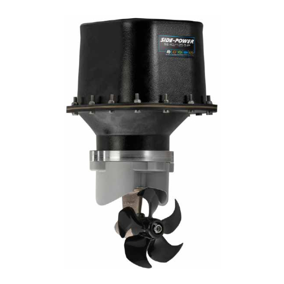
Sleipner motor as side-power se 40/125 s ip outboard motor
Hide thumbs
Also See for Side-Power SE 40:
- Installation and user manual (28 pages) ,
- Operational user manual (12 pages)
Table of Contents
Advertisement
Quick Links
SIDE-POWER
Thruster Systems
Installation and user manual
SLEIPNER MOTOR AS
P.O. Box 519
N-1612 Fredrikstad
Norway
Tel: +47 69 30 00 60
Fax: +47 69 30 00 70
SE 40/125 S IP
Ignition Protected
thruster assembly
w w w . s i d e - p o w e r . c o m
s i d e p o w e r @ s l e i p n e r. n o
© Sleipner Motor AS 2014
Advertisement
Table of Contents

Subscribe to Our Youtube Channel
Related Manuals for SLEIPNER MOTOR AS Side-Power SE 40


Summary of Contents for SLEIPNER MOTOR AS Side-Power SE 40
- Page 1 . s i d e - p o w e r . c o m Fax: +47 69 30 00 70 s i d e p o w e r @ s l e i p n e r. n o © Sleipner Motor AS 2014...
-
Page 2: Table Of Contents
DECLARATION OF CONFORMITY Stern thruster installation considerations ......3 Stern thruster installation considerations........3 Bolt on installation ..............4 We, Sleipner Motor AS We, Sleipner Motor AS Bolt on installation ..............4 Mould on installation ............... 5 P.O. Box 519 P.O. -
Page 3: Planning And Important Precautions
/ classification rules. The instructions in this guide can not be guaranteed to comply with all different regulations / classification rules. NB ! Faulty installation of the tunnel, thruster or panel will render all warranty given by Sleipner Motor AS void. Stern thruster installation considerations To achieve maximum effect, reliability and durability from your Sidepower stern thruster, a correct installation is very important. -
Page 4: Bolt On Installation
SEALANT Fig. 1 Fig. 2 WASHERS LOCKNUT OR DOU- BLE NUTS SEALANT Bolt on installation of the stern tunnel 1. Make sure that there are enough space both inside and out- side the transom of the boat. If a bow thruster is also installed, we strongly advice to use separate battery banks for the two thrusters to avoid 2. -
Page 5: Gearhouse And Motorbracket
Fig. 1 Fig. 2 Bolt tightening forces: Bolts (2x) holding gearhouse to bracket: 17 Nm (12,4 lb/ft) Designed by Material Type Date Drawing nr Tolerance NS-ISO 2768-1 R. Hansen SM-101539 13.09.2011 Copyright All rights reserved Title SL E IP N E R M O T O R A S Part nr Weight Size... - Page 6 Fig. 1 Thread glue Fitting propellers 1. Push the propeller on to the shaft and turn until the internal spline in the propeller hub aligns with the external spline on the propeller shaft. 2. Push the propeller onto the shaft with the track for the drivepin in an horizontal position (same direction as you set the drivepin), all the way in.
-
Page 7: Electromotor Ip Assembly
Fig. 2 Fig. 1 Designed by Material Type Date Drawing nr Tolerance NS-ISO 2768-1 R. Hansen SM-101539 13.09.2011 Designed by Material Type Date Drawing nr Tolera R. Hansen 13.09.2011 SM-101539 Copyright All rights reserved Title Copyright All rights reserved Title SL E IP N E R M O T O R A S SLE IPN E R M O TO R A S Part nr... -
Page 8: Electrical Installation
RED: Battery Date Drawing nr Designed by Material Type Tolerance NS-ISO 2768-1 R. Hansen 30.08.2011 SM-101462 Battery & cable recommendations: Copyright All rights reserved Title Model Voltage Nominal Min. battery >7m total + & - 7-14m total + & - 15-21m total + &... -
Page 9: Control Panel And Control-Leads
Pin configuration in contacts SIDEPOWER SIDEPOWER THRUSTER THRUSTER Connect round end SLEIPNER SLEIPNER of control adapter cable to the round socket on IP casing Control panel and control-leads Control panel and control-leads • You can install as many panels as you wish by using optional Y-connectors. If two or more panels are operated at the same time in •... -
Page 10: "Visual" Wiring Diagram
"Visual" wiring diagram "Visual" wiring diagram SE 40/125S ignition protected thruster assembly version 1.4 - 2014 SP55S2i ignition protected thruster assembly 1.1 - 2006... -
Page 11: Technical Wiring Diagram
Technical wiring diagram Round 4 pin connector on motor Motor housing connector Fused blue 9 red (+) inside 1A (sig -) blue (sig +) Electronic interface box 6 1232i white black (-) grey (sig +) grey (sig -) black brown Battery Fuse main... -
Page 12: Checklist
Checklist Propeller is fastened correctly to the shaft. Propeller turns freely in tunnel. The anode holding screw is tightened well with thread glue. All electrical wiring, cable sizes and battery capacity is according to the thruster installation manual. ... -
Page 13: Important User Precautions
Important user precautions Ensure that you know the location and how to operate the main battery switch and that disconnects the thruster from all power sources (batteries) so that the thruster can be turned off in case of a malfunction. ... -
Page 14: How To Use Sidepower Thrusters
To turn panel ON Turn boat to port Bow+Stern Thruster To turn panel OFF Turn boat to starboard How to use Sidepower thrusters How to use a bow thruster How to use a bowthruster 1. Turn main power switch for the bow thruster on. (Always turn off the main power switch when not on board.) 1. -
Page 15: Maintenance
Electromotor assembly Composite 5-blade propeller for ultimate performance. Pre-filled lifetime lubricated gearhouse. Changeable anode protects gearhouse from corrosion in seawater. Thread glue Fastening screw for anode Anode Propeller lock nut Washer Drivepin for propeller Maintenance » Keep the propeller and gearhouse clean from growth by painting with antifouling before every season. PS ! The anode, sealing and propeller shafts must absolutely not be painted. -
Page 16: Troubleshooting
Troubleshooting Before seeking assistance at the help desk of your Sidepower dealer / distributor please perform these tests and make notes of all measurements to ensure that they have as much information as possible to work on. NB! All check points and solutions must be carried out after consulting the relevant information elsewhere in this manual to under- stand how the system is intended to work. -
Page 17: Warranty Statement
Warranty statement 1. The equipment manufactured by Sleipner Motor AS (The “Warrantor”) is warranted to be free from defects in workmanship and mate- rials under normal use and service. 2. This Warranty is in effect for of two years from the date of purchase by the user. Proof of purchase must be included, to establish that it is inside the warranty period. -
Page 18: Parts List
SP 40 S2i PARTS LIST - SE 40/125 S SP 30 S2i / SP 40 S2i / SP 55 S2i SE 40/125S ignition protected thruster assembly 3.7 - 2006 version 1.4 - 2014... - Page 19 Worldwide sales and service www.side-power.com SLEIPNER MOTOR AS P.O. Box 519 N-1612 Fredrikstad Norway Tel: +47 69 30 00 60 Fax:+47 69 30 00 70 www.side-power.com sidepower@sleipner.no...
Need help?
Do you have a question about the Side-Power SE 40 and is the answer not in the manual?
Questions and answers