
Related Manuals for SLEIPNER MOTOR AS SE 50 S IP


Summary of Contents for SLEIPNER MOTOR AS SE 50 S IP
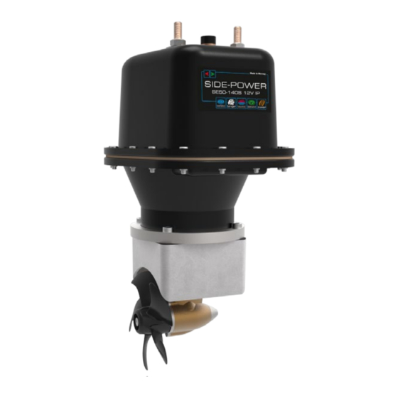
- Page 1 SE 50/140 S IP Ignition Protected SIDE-POWER thruster assembly Thruster Systems Installation and user's manual SLEIPNER MOTOR AS P.O. Box 519 N-1612 Fredrikstad Norway www.side-power.com © Sleipner Motor AS 2017...
-
Page 2: Table Of Contents
Warranty statement .............. 23 Spareparts list & drawing ............ 24 Service centres ..............28 DECLARATION OF CONFORMITY We, Sleipner Motor AS P.O. Box 519 N-1612 Fredrikstad, Norway declare that this product with accompanying standard remote control systems complies with the essential health and safety requirements according to the Directive 93/68/EEC. -
Page 3: Technical Specifications
Technical specifications Motor: Custom made reversible DC-motor. Gearhouse: Seawater resistant bronze. Ball bearing at propeller shaft; combination of ball bearing and slide bearing at driveshaft. Motor bracket: Seawaterresistant aluminium. Ignition protection: Conforms to ISO 8846 Propeller: 5-blade Skew-back design "Q-prop" propeller, reinforced composite. Batteries: Minimum recommended battery capacity (cold crank capacity by DIN standard) See table... -
Page 4: Planning & Important Precautions
/ classification rules. The instructions in this guide can not be guaranteed to comply with all different regulations / classification rules. NB ! Faulty installation of the tunnel, thruster or panel will render all warranty given by Sleipner Motor AS void. SE 50/140S ignition protected thruster assembly... -
Page 5: Positioning Of The Tunnel / Thruster
Fig. 1 Pivot Fig. 3 point B = 10,0m A = 11,0m Fig. 2 Fig. 4 Ø Positioning of the tunnel / thruster Positioning of the tunnel / thruster Positionierung von Tunnel / Thruster The Thruster should be as far forward as possible (Fig. 1) The Thruster should be as far forward as possible (Fig. -
Page 6: How To Shape The Tunnel Ends
Fig. 1 Fig. 2 R = 0,1 x D (10%) R = 0,1 x D (10%) � � � � � ☺ ☺ ☺ ☺ ☺ Fig. 3 Fig. 4 Tunnel ends Tunnel ends Formgebung der Tunnelenden Rounded tunnel ends will maximize thrust and minimize Abgerundete Tunnelenden erhöhen die Schubkraft und Rounded tunnel ends will maximize thrust and minimize noise. -
Page 7: How To Prevent Drag From Tunnel Installation
Fig. 1 Fig. 2 Fig. 3 ☺ ☺ ☺ ☺ ☺ � � � � � ☺ ☺ ☺ ☺ ☺ Prevent drag from tunnel Optimaler Strömungsverlauf am Rumpf Prevent drag from tunnel A possible problem in sailboats or fast powerboats is that they get a Segelboote und sehr schnelle Booten können gelegentlich durch A possible problem in sailboats or fast powerboats is that they get a drag from the back face of the tunnel, as this becomes a “flat”... -
Page 8: Possible Tunnel Installation In Sailboats
Fig. 1 � � � � � ☺ ☺ ☺ ☺ ☺ Pos. A Pos. B � � � � � ☺ ☺ ☺ ☺ ☺ Tunnel installation in sailboats Installation in Segelbooten Tunnel installation in sailboats Many sailboats have a racing type hull which means that it is very flat bottomed and has a very shallow draft in the bow section. It is thereby very difficult Many sailboats have a racing type hull which means that it is very Segelboote weisen häufig einen Rumpf in Rennform auf, was not to say impossible to fit a tunnel thruster the usual way, at least as far forward in the hull as a thruster should be (Fig. -
Page 9: Tunnel Installation In A Grp Boat
Fig. 1 Fig. 2 Fig. 3 Fig. 4 Tunnel installation We recommend that a professional does the fibreglass fitting of the tunnel. These instructions are only general, and do not explain in any way the details of fibreglass work. Problems caused by faulty installation of the tunnel, are the installers full responsibility. Find the position in the boat considering the information given earlier in this manual and the applicable measurements for the thruster model you are installing. - Page 10 Fig. 1a Fig. 1c Fig. 1 Fig. 1b Fig. 1d Fig. 3 Fig. 2 R = D x 0,1 R = D x 0,1 Tunnel installation Tunnelinstallation Tunnel installation Soften the edges with a radius of 10% of the tunnel diameter (Fig. Runden Sie die Kanten mit einem Radius (10% des Tunneldurch- Soften the edges with a radius of 10% of the tunnel diameter (Fig.
-
Page 11: Gearhouse And Motorbracket
Fig. 1 Fig. 3b Fig. 4a Fig. 2 Fig. 4b Fig. Fig. 5 Fitting gearhouse and motor bracket Mark the centreline of the tunnel and the boats centreline. The gearhouse and propeller must be fitted as shown above for the thrust direction to correspond with the control panel Fig. -
Page 12: Fitting The Propeller
Fig. 1 Fig. 2 Fitting propeller 1. SE50/140S IP: Push the propeller (3) onto the shaft, carefully rotate the propeller shaft until the drive pin (4) aligns and moves into the slot/groove in the propeller hub. There should be almost no gap (approximately 1mm) between the propeller hub and the gear house. Fig 1. 2. -
Page 13: Electromotor
Fig. 2 Fig. 1 Fig. 3 Fig. 1b Fitting the electromotor Turn the driveshaft in the gearhouse and the motor shaft so the track for the shear pin has a corresponding direction with the shear pin in the motor coupling. Fig 2. Use the enclosed template to measure the driveshaft has come through the motor bracket with the correct height Fig 1b. Slide the motor gently onto the driveshaft and motor bracket. -
Page 14: Electrical Installation
Battery Thruster Thruster Thruster 12V or motor motor motor Battery 12V or RED + Thruster motor Isolation cap (IP model) Battery & cable recommendations: <7m total 7-14m total 15-21m total 22-28m total 28-35m total 36-45m total + & - + & - + &... -
Page 15: Control Panel And Control-Leads
Pin 2 Pin 3 Pin 4 Pin 2 Pin 3 Pin 4 Connect round end of control adapter cable to the round socket on IP casing Thruster motor 12/24 V (IP model) Control panel and control-leads Control panel installation: See control panel manual •... -
Page 16: "Visual" Wiring Diagram
"Visual" wiring diagram "Visual" wiring diagram SE 50/140S ignition protected thruster assembly version 1.0.0 - 2017 SP55S2i ignition protected thruster assembly 1.1 - 2006... -
Page 17: Technical Wiring Diagram
Technical wiring diagram Round 4 pin connector on motor Motor housing connector Fused blue 9 red (+) inside 1A (sig -) blue (sig +) Electronic interface box 6 1232i white black (-) grey (sig +) grey (sig -) black brown Battery Fuse main... -
Page 18: Checklist For Control Of The Installation
Checklist Propeller is fastened correctly to the shaft. Propeller turns freely in tunnel. The anode holding screw is tightened well with thread glue. All electrical wiring, cable sizes and battery capacity is according to the thruster installation manual. ... -
Page 19: Important User Precautions
Important user precautions • Ensure that you know the location of the main battery switch that disconnects the thruster from all power sources (batteries) so that the thruster can be turned off in case of a malfunction. • Always turn the main power switch off before touching any part of the thruster, as an incidental start while touching moving parts can cause serious injuries. -
Page 20: How To Use Side-Power Thrusters
To turn panel ON Turn boat to port Turn boat to port (Stern) To turn panel OFF Turn boat to starboard Turn boat to starboard (Stern) Bow+Stern Thruster How to use Side-Power thrusters How to use a bowthruster 1. Turn main power switch for the bowthruster on. (Always turn off the main power switch when not onboard.) 2. -
Page 21: Maintenance & Service
1.Fastening screw for anode 2. Anode 3. Propeller lock nut 4. Washer 5. Drive pin 6. Flexible coupling Maintenance » Retighten the bolts holding the gearhouse to the motor bracket during the first on-land service with the specified bolt tightening force (see page 13). »... -
Page 22: Troubleshooting
Troubleshooting Before seeking assistance at the help desk of your Side-Power dealer / distributor please perform these tests and make no- tes of all measurements to ensure that they have as much information as possible to work on. NB! All check points and solutions must be carried out after consulting the relevant information elsewhere in this manual to under-stand how the system is intended to work. -
Page 23: Warranty Statement
Warranty statement 1. The equipment manufactured by Sleipner Motor AS (The “Warrantor”) is warranted to be free from defects in workmanship and materials under normal use and service. 2. This Warranty is in effect for of two years (Leisure Use) or one year (Commercial use) from the date of purchase by the user. Proof of purchase must be included, to establish that it is inside the warranty period. -
Page 24: Spareparts List & Drawing
SPARE PARTS In order to present the most up to date documentation, we advise you to go to our website www.side-power.com and locate your product to find relevant spare parts. SE 50/140S ignition protected thruster assembly version 1.0.0 - 2017... - Page 25 SE 50/140S ignition protected thruster assembly version 1.0.0 - 2017...
- Page 26 SE 50/140S ignition protected thruster assembly version 1.0.0 - 2017...
- Page 27 SE 50/140S ignition protected thruster assembly version 1.0.0 - 2017...
-
Page 28: Service Centres
SLEIPNER MOTOR AS P.O. Box 519 N-1612 Fredrikstad Norway The information given in the document was correct at the time it was published. However, Sleipner Motor AS can not accept liability for any inaccuracies or omissions it may contain. Continuous product improvement may change the product specifications without notice. Therefore, Sleipner Motor AS can not accept liability for any pos-...
Need help?
Do you have a question about the SE 50 S IP and is the answer not in the manual?
Questions and answers