Table of Contents
Advertisement
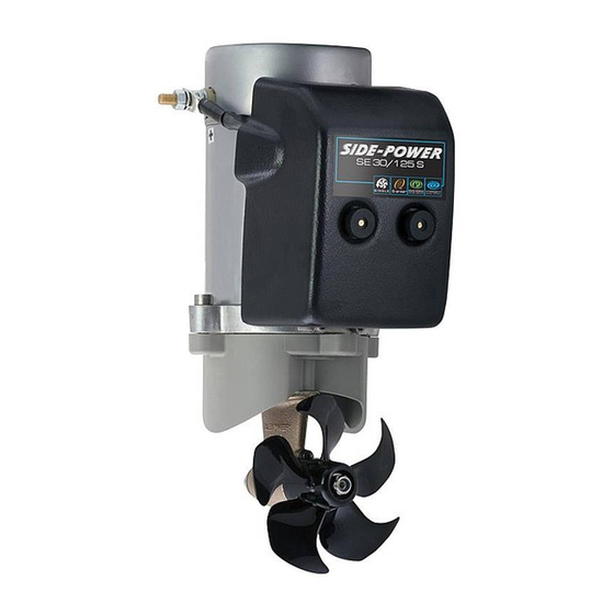
SIDE-
POWER
Thruster systems
Installation and user's manual
GB
Installasjons og brukermanual
N
SLEIPNER MOTOR AS
P.O. Box 519
N-1612 Fredrikstad
Norway
Tel:
Fax:
+47 69 30 00 60
+47 69 30 00 70
SE 30/125 S
SE 40/125 S
SE 60/185 S
w w w . s i d e - p o w e r . c o m
s i d e p o w e r @ s l e i p n e r. n o
© Sleipner Motor AS 2008
Advertisement
Table of Contents

Related Manuals for SLEIPNER MOTOR AS SE 30


Summary of Contents for SLEIPNER MOTOR AS SE 30
- Page 1 . s i d e - p o w e r . c o m Fax: +47 69 30 00 70 s i d e p o w e r @ s l e i p n e r. n o © Sleipner Motor AS 2008...
-
Page 2: Table Of Contents
Direk- tiv 89/336/eeC Fra 23 mai 89, korrigert av 92/31/eeC og 93/68/eeC. SE 30/125 S - SE 40/125 S - SE 60/185 S 1.0.1- 2008... -
Page 3: Technical Specifications
3 minutes. 3 minutes. SE 30/125 S - SE 40/125 S - SE 60/185 S SP 30 S2i / SP 40 S2 i/ SP 55 S2i 3.7 - 2006 1.0.1- 2008... -
Page 4: Planning & Important Precautions
I de tilfeller båter skal godkjennes eller klassifiseres i henhold til internasjonal, eller spesielle standarder, er montør ansvarlig for at de gjeldende lover og regelverk følges. Sleipner Motor AS kan ikke garantere at instruksjonene i denne manualen er i henhold til alle gjeldende regelverk og standarder. -
Page 5: Positioning Of The Tunnel / Thruster
6 to 7 times the tunnel diameter as the reduziert wird. reduction is then clearly noticeable. performance reduction is then clearly noticeable. SE 30/125 S - SE 40/125 S - SE 60/185 S SP 75 Ti / SP 95 Ti / SP 125 Ti 1.0.1- 2008 2.5.1- 2007... -
Page 6: How To Shape The Tunnel Ends
ähnlich positiven Auswirkungen wie eine Abrundung verbunden (siehe Seite 20, Fig. 1b & 1d). SE 30/125 S - SE 40/125 S - SE 60/185 S SP 75 Ti / SP 95 Ti / SP 125 Ti 1.0.1- 2008... -
Page 7: How To Prevent Drag From Tunnel Installation
20. Geräuschentwicklung des Thrusters weitgehend abzurunden. Weitere Informationen siehe Seite 20. SE 30/125 S - SE 40/125 S - SE 60/185 S SP 75 Ti / SP 95 Ti / SP 125 Ti 1.0.1- 2008... -
Page 8: Possible Tunnel Installation In Sailboats
Tunnelöffnungen im Rumpf zu vermeiden. to avoid extremely long tunnels and huge oval tunnel openings in the hull. SE 30/125 S - SE 40/125 S - SE 60/185 S SP 75 Ti / SP 95 Ti / SP 125 Ti 1.0.1- 2008... -
Page 9: Tunnel Installation In A Grp Boat
SE 30/125 S - SE 40/125 S - SE 60/185 S 1.0.1- 2008... - Page 10 PS! Avoid all casting where the motor-bracket is to be placed, as this will cause misfit and possible failure of the gearhouse. SE 30/125 S - SE 40/125 S - SE 60/185 S SP 30 S2i / SP 40 S2 i/ SP 55 Si 1.0.1- 2008...
-
Page 11: Thruster Installation Gearhouse And Motorbracket
(Fig. 7). SP 30 S2i / SP 40 S2 i/ SP 55 Si 3.5 - 2005 SE 30/125 S - SE 40/125 S - SE 60/185 S SP 30 S2i / SP 40 S2 i/ SP 55 S2i 1.0.1- 2008... -
Page 12: Oil Tank & Propeller
2: Sinkanode 2: Zincanode 3: Låsemutter til propell 3: Propeller lock nut 4: Skive til propell 4: Washer 5: Drivpinne for propell 5: Drive pin for propeller SE 30/125 S - SE 40/125 S - SE 60/185 S 1.0.1- 2008... -
Page 13: Electromotor
This cover must be removed before the thruster is being used. SE 30/125 S - SE 40/125 S - SE 60/185 S 1.0.1- 2008... -
Page 14: Electrical Installation
(A1) terminal on the motor. If you feel unsure on how to perform this check, contact skilled personnel for guidance. SE 30/125 S - SE 40/125 S - SE 60/185 S 1.0.1- 2008... -
Page 15: Control Panel And Control-Leads
Aktiverer thruster rele Babord Pin2: BLUE Engages thruster SB solenoid Pinne 4: Rød Pluss til kontrolpanel Pin3: GREY Engages thruster Port solenoid Pin4: Positive voltage for control panel SE 30/125 S - SE 40/125 S - SE 60/185 S 1.0.1- 2008... -
Page 16: Visual Wiring Diagram
6 1232i (ex. 6 122x) the 6 1232i (ex. 6 122x) on SP75Ti, SP95Ti, and SP125Ti. SP 75 Ti / SP 95 Ti / SP 125 Ti SE 30/125 S - SE 40/125 S - SE 60/185 S 2.5.1- 2007 1.0.1- 2008... -
Page 17: Technical Wiring Diagram
6 1232i (ex. 6 122x) the 6 1232i (ex. 6 122x) on SP75Ti, SP95Ti, and SP125Ti. SE 30/125 S - SE 40/125 S - SE 60/185 S SP 75 Ti / SP 95 Ti / SP 125 Ti 1.0.1- 2008 2.5.1 - 2007... -
Page 18: Checklist For Control Of The Installation
Skottet hvor thrusteren er montert er isolert fra kjølvann og har ingen water and has no obvious or suspected risks for flooding. åpenbar risiko for lekkasje. Other comments by installer: Kommentar fra installør: SE 30/125 S - SE 40/125 S - SE 60/185 S 1.0.1- 2008... -
Page 19: Important User Precautions
• Never store anything (e.g. equipment, sails, ropes etc.) in the same compartment as the thruster. When the thruster runs for a longer period it will get hot and will cause damage. SE 30/125 S - SE 40/125 S - SE 60/185 S 1.0.1- 2008... -
Page 20: How To Use Sidepower Thrusters
• Again, if in doubt, try in open water first! • Again, if in doubt, try in open water first! SE 30/125 S - SE 40/125 S - SE 60/185 S SP 30 S2i / SP 40 S2 i/ SP 55 Si 1.0.1- 2008... -
Page 21: Maintenance & Service
• Make sure that your batteries are in a good condition so that the thruster gets a good voltage. Old or bad batteries will give a reduced performance from the thruster. SE 30/125 S - SE 40/125 S - SE 60/185 S 1.0.1- 2008... -
Page 22: Troubleshooting
Shut off thruster main switch, tap slightly on the solenoid to see if it will release. Turn Solenoid lock-in, auto stop of thruster, auto retry every 10 on thruster main switch. If solenoid is still in lock-in mode, replace solenoid. seconds. SE 30/125 S - SE 40/125 S - SE 60/185 S 1.0.1- 2008... -
Page 23: Warranty Statement
10 sekund for å se om feilen å se om kontaktflatene slipper. Slå på hovedstrømbryter og se om feilen er fikset. Om er rettet. den vedvarer må relé byttes. SE 30/125 S - SE 40/125 S - SE 60/185 S 1.0.1- 2008... -
Page 24: Spareparts List & Drawing
Warranty statement 1. The equipment manufactured by Sleipner Motor AS (The “Warrantor”) is warranted to be free from defects in workmanship and materials under normal use and service. 2. This Warranty is in effect for of two years from the date of purchase by the user. Proof of purchase must be included, to establish that it is inside the warranty period. - Page 25 SP 30 S2i PARTS LIST - SE 30/125 S SP 30 S2i / SP 40 S2 i/ SP 55 S2i 3.7 - 2006 SE 30/125 S - SE 40/125 S - SE 60/185 S 1.0.1- 2008...
- Page 26 SP 40 S2i PARTS LIST - SE 40/125 S SP 30 S2i / SP 40 S2i / SP 55 S2i 3.7 - 2006 SE 30/125 S - SE 40/125 S - SE 60/185 S 1.0.1- 2008...
- Page 27 PARTS LIST - SE 60/185 S SE 30/125 S - SE 40/125 S - SE 60/185 S 1.0.1- 2008...
-
Page 28: Service Centres
Tel: +385 51 704 500 Sleipner Motor AS Fax: +385 51 704 600 acy@net.hr Sleipner Motor AS • P. O. Box 519, N-1612 Fredrikstad • Norway Tel: +47 69 30 00 60 • Fax: +47 69 30 00 70 • sidepower@sleipner.no • www.side-power.com...
Need help?
Do you have a question about the SE 30 and is the answer not in the manual?
Questions and answers