Table of Contents
Advertisement
Quick Links
FILE NO. 400-200604GR
SERVICE MANUAL
HARD DISK C A M E R A
GSC-R60/GSC-R30
The above models are classified as green products (*1).
This Service Manual describes replacement parts for the
green products. When repairing these greenproduct(s), use
the part(s) described in this manual and lead-free solder (*2).
For (*1) and (*2), see the next page.
DOCUMENT CREATED IN JAPAN, MARCH, 2006
CREATED IN JAPAN, March, 2006
S
Advertisement
Table of Contents
Troubleshooting

Related Manuals for Toshiba GSC-R60


Summary of Contents for Toshiba GSC-R60
- Page 1 FILE NO. 400-200604GR SERVICE MANUAL HARD DISK C A M E R A GSC-R60/GSC-R30 The above models are classified as green products (*1). This Service Manual describes replacement parts for the green products. When repairing these greenproduct(s), use the part(s) described in this manual and lead-free solder (*2).
- Page 2 Hazardous Substances. From July 1, 2006, the RoHS Directive will prohibit any marketing of new products containing the restricted substances. Increasing attention is given to issues related to the global environmental. Toshiba Corporation recognizes environmental protection as a key management tasks, and is doing its utmost to enhance and improve the quality and scope of its environmental activities.
-
Page 3: Table Of Contents
Contents 1. Product Outline......3 5. Disassembly / Assembly....27 1-1. Appearance Monaural......3 5-1. Disassembly..........27 1-2. Photography Mode........4 5-2. Assembly..........34 1-2-1. OSD..............4 1-2-2. Main key operations........5 6. Adjustment.........41 1-3. Playback Mode.........6 6-1. Items to adjust........41 1-3-1.OSD...............6 6-2. Devise to Use.........41 1-3-2. Main key operation........7 6-3. -
Page 4: Product Outline
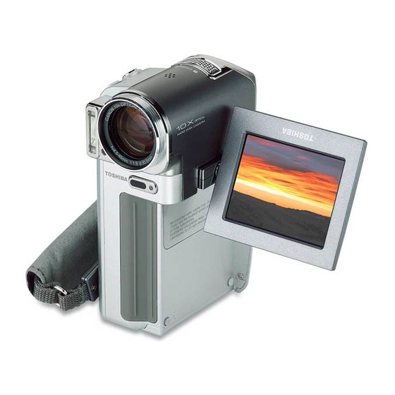
1. Product Outline Microphone Speaker 1-1. Appearance Stereo Monaural Still REC button Zoom lever Also use for level change Lens at playback. 10x optical zoom Auxiliary light 2 LED lamps Flash Grip belt Auxiliary light button STATUS LED MEDIA LED Backlight adjustment button Terminal cover DC IN 10V terminal... -
Page 5: Photography Mode
1-2. Photography Mode 1-2-1. OSD Enter the photography mode by sliding mode lever to the photography side. Battery level gauge Indicator - Videos Time remained for video shooting Indicator – still images Number of still images can be taken Zoom bar Focus Scene Flash... -
Page 6: Main Key Operations
1-2-2. Main key operations Focus setting Video REC start Zoom Flash setting Exposure bias setting Zoom Video OK up OK left OK Right Press Still REC Half push MENU down AF/AE lock OSD details display Recording menu Scene setting... -
Page 7: Playback Mode
1-3. Playback Mode 1-3-1.OSD Enter the playback mode by sliding mode lever to the playback side. Video Still image Playback mode Battery level gauge Recoding date and time Drive Album File number Previous image Next image Playback mode Video icon Video record time Guide... -
Page 8: Main Key Operation
1-3-2. Main key operation Chapter selection Zooming playback Video playback No OSD indication Information display OK押 Press Press OK up OK left OK right JOG left JOG right Display previous Display next image image OK down OK down MENU MENU Video playback method Thumbnail display Rotation display... -
Page 9: Video Playback With Tricks
1-3-3. Video Playback with Tricks High-speed High-speed Fast Forward rewinding DOWN DOWN JOG-L DOWN JOG-R JOG-L JOG-R JOG-R/U JOG-L/UP Rewinding Playback Fast Forward LEFT RIGHT DOWN JOG-L JOG-R Frame rewind Pause Frame playback Playback Pause F. Forward (3x) F. Forward (15x) Rewinding (3x) Rewinding (15x) MODE-R... -
Page 10: Usb Mode
1-4. USB Mode The USB mode becomes available by following two procedures below. 1) Connect the AC adaptor to the cradle, and connect PC to the cradle with a USB cable. Set the camera on the cradle, and then press the USB button located on the cradle. 2) Attach the connection adapter to the camera. -
Page 11: Lan Mode
1-5. LAN Mode Connect the AC adapter to the cradle then connect the cradle via a LAN cable to the RD that has "Dubbing through network" function. The LAN mode becomes available by pressing the LAN button on the cradle. Connection completed Press OK... -
Page 12: Mechanical Parts
2. Mechanical Parts 2-1. Explode Diagram GSC-R60... - Page 13 GSC-R30...
-
Page 14: Camera Part List
2-2. Camera Part List Photo Part Cord Part Name Purchase Code Mechanical Parts Main Cover AA01 P000461920 ASSY P000462420 (GSC-R60) Left Cover AA02 ASSY P000462300 (GSC-R30) Top Cover AA06 P000461930 ASSY Lens Cover AA11 P000461940 ASSY Back Cover AA08 P000461950... - Page 15 Battery Case AC11 P000461980 ASSY A110 Screw Cap P000461990 A306 Lens Cushion P000462000 P000462450 (GSC-R60) A703 Rating Label P000462330 (GSC-R30) A706 SN Label P000462010 P000462430 (GSC-R30) Protection A316 Rubber P000462310 (GSC-R30) for GSC-R60 P000462440 A358 Protection Gel for GSC-R30 P000462320...
- Page 16 Photo Part Cord Part Name Purchase Code Speaker A320 P000462020 Cushion Shield Gasket A355 P000462030 Shield Gasket A356 P000462040 HDD Case AC15 Not Service Part ASSY HDD Cover AC40 Not Service Part ASSY A305 Lens Holder Not Service Part Flash Plate AC12 Not Service Part ASSY...
- Page 17 Photo Part Cord Part Name Purchase Code A313 LCD Plate Not Service Part Thermal Sheet A346 Not Service Part Thermal Sheet A347 Not Service Part A349 EMI Sheet A Not Service Part A350 EMI Sheet B Not Service Part A351 EMI Sheet C Not Service Part A900...
- Page 18 Photo Part Cord Part Name Purchase Code HA54 LCD ASSY P000462070 P000462460 (GSC-R30) HA5A HDD ASSY P000462340 (GSC-R30) Microphone HA56 P000462080 ASSY HA55 Speaker ASSY P000462090 FLASH-MAIN W999 P000462170 PCB Assembly MAIN PCB U001 P000462100 ASSY FLASH PCB UA51 P000462110 ASSY JACK PCB UA02...
- Page 19 Photo Part Cord Part Name Purchase Code SENSOR PCB U006 P000462130 ASSY TERMINAL UA11 P000462140 PCB ASSY 3-WAY FPC U008 P000462150 ASSY LENS-MAIN UA09 P000462160 FPC ASSY...
-
Page 20: Screw List
2-3. Screw List Details of the "Screw Kit" (A900) TOTAL : 39 screws No. Part Code Specification Head D Head T Plating Positon used A324 M1.4x2.0 Ni(Silver) Top Cover ASSY (AA06) --- Flash Plate ASSY (AC12) FLASH PCB ASSY (UA51) --- Flash Plate ASSY (AC12) JACK PCB ASSY (UA02) --- Flash Plate ASSY (AC12) A325 M1.7x2.0... -
Page 21: System Overview
3. System Overview 3-1. System Block Diagram IC1404 DAC1/4/5 Y/C/VBS IC1001 K4S56323LF-HN75000 SDRAM ALR267FGX (SANYO) LC15009 2.5" LCD1/3 DV2UV[7:0] M172D MN39292FJ LENS Controler LCD2 1/3.6" 2.13 Mega Pixels Sip-1280 IC701 VSP2254GSJR IC3301 OLPF (1636 ×1220) 2.5 um LCD FLIP S W DA[13:0] CDS/ADC LCD LID OPEN... -
Page 22: Composition
3-2. Composition This product contains a camera and a cradle (option for R30). The camera consists of 4 PC boards (PCB_MAIN, PCB_CCD, PCB_BACK, PCB_JACK) and 8 FPCs (FPC_ZOOM, FPC_FRONT, FPC_HDD, FPC_LCD, FPC_STROBE, FPC_CRADLECON, FPC_HEAD, FPC-BACK), lens unit, color LCD, flash unit, 1.8 inch HDD, etc. -
Page 23: Cradle
MPEG2 compressed data to the image (YCrCb) signal. - SDRAM for MPEG operation A memory for MPEG2 coder operation. - Power supply It generates 5V, 2.5V, 3.3V for HDD, -8V, 13V, 3V for sub-microcomputer, 3.3V, 1.5V, 1.2V, 3.5V, 14V for LCD back light, 6V for auxiliary light from 3 power sources: 10V from DC jack, 10V from cradle, and battery. -
Page 24: Operation
FPC_TOP consists of connector that connects the camera and CRADLE main board. 3-3. Operation 3-3-1. Start-Up Operation From AC adapter The start-up operation begins by pressing the POWER button or by opening the LCD monitor while AC adapter is securing the power supply either from the DC jack on the camera or the cradle. (The status is monitored by UL33.) The 1.63 voltage will appear on the power monitor line (DCP) from the AC adapter of the sub-microcomputer on the POWER board while the AC adapter is securing the power supply. -
Page 25: Lan Communication
3-3-8. LAN Communication Under the LAN mode, DSP starts communicating with the LAN control IC. The LAN communication becomes possible by supplying the power to the analog section of the LAN controlling IC. In order to do so, it is required to turn the LANEN line to HIGH at the same time the DSP starting its communication. 3-3-9. -
Page 26: Troubleshooting
4. Troubleshooting Condition Analysis Solution Fuse F3201 disconnected Replace MAIN PCB ASSY (U001) The power does not (Short circuit in LAN system) turn on. Fuse F4201 disconnected (Short circuit in system power supply) Fuse F4301 disconnected (Short circuit in 5V power supply system) Fuse F4302 disconnected (Short circuit in SDRAM power supply system) Fuse F4303 disconnected... - Page 27 Condition Analysis Solution Unable to focus Lens defect Replace Lens Module ASSY (HA52) Perform AE readjustment Lens adjustment data defect Replace MAIN PCB ASSY (U001) FPC-ZOOM defect Replace Zoom Cover ASSY 10 Unable to shoot still (AA05) image MAIN board defect Replace MAIN PCB ASSY (U001) Flash unit defect Replace FLASH PCB ASSY...
-
Page 28: Disassembly/Assembly
5. Disassembly/Assembly Do not formatting the hard disk drive carelessly. Do not deleting the Image and other file in hard disk This camera has its own built-in hard disk drive. Since a user's personal information may be included in it, be careful of the handling of a file, and prevent the outflow of data etc. - Page 29 FPC. Detach the HDD ASSY (HA5A) This work is unnecessary when and Protection Rubber (A316*2). not exchanging HDD ASSY GSC-R60 - Detach the HDD (HA5A), Protection Rubber (A316*2) and Protection Gel ASSY (HA5A), Protection Rubber (A358*4).
- Page 30 Step Figure Discription Remark Take off the Screw Cap (A110) Pushing the lug with tweezers and and remove the screws A326. remove the Screw Cap (A110) from inner side. Open the LCD monitor and Remove the screws and close the remove the screws A331*2.
- Page 31 Step Figure Discription Remark Remove the Speaker Cushion This work is unnecessary when (A320). not exchanging Main Cover ASSY (AA01), Speaker ASSY (HA55) and Speaker Cushion (A320). Remove the connector of JACK This work is unnecessary when PCB ASSY (UA02) and take off not exchanging the Main Cover the Speaker ASSY (HA55).
- Page 32 Step Figure Discription Remark Remove the screws A326*3 and A331. Take off the Flash Plate ASSY (AC12) and Miceophone Plate (A152). Remove the screw A324. This work is unnecessary when Detach the Flash Plate ASSY not exchanging the FLASH PCB (AC12) and FLASH PCB ASSY ASSY (UA51).
- Page 33 Step Figure Discription Remark From the THERMINAL PCB ASSY TERMINAL PCB ASSY (UA11) (UA11) to the MAIN PCB ASSY ( does not separate yet at this time, U001) Connected FPC remove be careful not to cut FPC. from the connector and pull out the Cradle terminal from Main Cover ASSY (AA01).
- Page 34 Step Figure Discription Remark Remove the screw A331. Detach This work is unnecessary when the Battery Case ASSY (AC11) not exchanging the Battery Case and SENSOR PCB ASSY (U006). ASSY (AC11) and SENSOR PCB ASSY (U006). Remove the Thermal Sheet A This work is unnecessary when (A346) from the Battery Case not exchanging the Battery Case...
-
Page 35: Assembly
5-2. Assembly Step Figure Discription Remark Install the FPC of LCD ASSY Be careful of direction of the hinge (HA54) insert the hole of Main of LCD ASSY (HA54). Cover ASSY (AA01). Tighten screws certainly so that Use the screws A328*2 and there is no slack. - Page 36 Step Figure Discription Remark The EMI Sheet C (A351) is put in the convex for positioning of a Main Cover ASSY (AA01), and it fixes. Connect the lead wire and FPC of Battery Case ASSY (AC11) to MAIN PCB ASSY (U001). Set the MAIN PCB ASSY (U001) Be careful, the lead wire from a to body.
- Page 37 Step Figure Discription Remark Open the Battery Cover. Use Check the switch lever moves screw A325 and install the Switch when the battery cover that open PCB of the TERMINAL PCB and close. ASSY (UA11). Be careful not to cut FPC. Connect the TERMINAL PCB ASSY (UA11) of FPC to MAIN PCB ASSY (U001).
- Page 38 Step Figure Discription Remark The Lens block is fixed with Use screw A331 for Lens side and screws A331 and A332. screw A332 for LCD side. A331 A332 Connect the FPC from the Lens Module ASSY (HA52) to Main Cover ASSY (U001). Install the FLASH PCB ASSY Check that the insulated sheet (UA51) to the Flash Palte ASSY...
- Page 39 Step Figure Discription Remark FLASH-MAIN FPC (W999) from a A lead wire through between a MAIN PCB ASSY (U001) is connector and IC as shown. connected to the connector of a Do not overlap to other parts. FLASH PCB ASSY (UA51). The lead wire from a JACK PCB ASSY (UA02) is connected to the connector of a MAIN PCB ASSY.
- Page 40 Step Figure Discription Remark Back Cover ASSY (AA08) is fixed with a screw A326. Open the LCD and Back Cover After tightening a screws, close ASSY (AA08) is fixed with a the LCD monitor. screws A331*2. Stuck on the Thermal Sheet B (A347*2) as shown.
- Page 41 Step Figure Discription Remark Connect the HDD ASSY (HA5A) of FPC to connector, set the HDD inside of the HDD Case ASSY (AC15). Install the HDD Cover ASSY Unite four projection portions of (AC40). the HDD Cover ASSY (AC40) to a hollow portion of HDD Case ASSY (AC15).
-
Page 42: Adjustment
- Power supply (AC adapter, accessories) - Lens hood Model name: MEHLH1 (attached to MEHV10) - SD card Capacity: 8MB or greater - Adjustment firmware * File name: ADJR20.bin (provided by Toshiba) - Firmware for update * File name: GSCR20.bin and UP_R20.bin (provided by Toshiba) -
Page 43: Adjustment Procedure
6-3. Adjustment Procedure 6-3-1. CCD2CH Adjustment (CCD2CH) Devices to use: - Dedicated power supply (accessory) - Lens hood - SD card The SD card needs to contain the adjustment firmware. Make sure the firmware is written to root directory. - Standard light source It takes several minutes to stabilize the luminosity. -
Page 44: Ccd Sensitivity (Sensitive)
6-3-2. CCD Sensitivity (SENSITIVE) Devices to use: - Dedicated power supply (accessory) - Lens hood - SD card The SD card needs to contain the adjustment firmware. Make sure the firmware is written to root directory. - Standard light source It takes several minutes to stabilize the luminosity. -
Page 45: Iris/Nd
6-3-3. IRIS/ND Devices to use: - Dedicated power supply (accessory) - Lens hood - SD card The SD card needs to contain the adjustment firmware. Make sure the firmware is written to root directory. - Standard light source It takes several minutes to stabilize the luminosity. Start the adjustment after waiting for at least 10 minutes after turning the power on. -
Page 46: Shutter
6-3-4. Shutter Devices to use: - Dedicated power supply (accessory) - Lens hood - SD card The SD card needs to contain the adjustment firmware. Make sure the firmware is written to root directory. - Standard light source It takes several minutes to stabilize the luminosity. Start the adjustment after waiting for at least 10 minutes after turning the power on. -
Page 47: Ccd Defect Pixel
6-3-5. CCD Defect Pixel * Devices to use: - Dedicated power supply (accessory) - Lens hood - SD card The SD card needs to contain the adjustment firmware. Make sure the firmware is written to root directory. - Standard light source It takes several minutes to stabilize the luminosity. -
Page 48: White Balance
6-3-6. White Balance Devices to use: - Dedicated power supply (accessory) - Lens hood - SD card The SD card needs to contain the adjustment firmware. Make sure the firmware is written to root directory. - Standard light source It takes several minutes to stabilize the luminosity. Start the adjustment after waiting for at least 10 minutes after turning the power on. -
Page 49: Zoom/Focus
6-3-7. Zoom/Focus Devices to use: - Dedicated power supply (accessory) - Lens hood - SD card The SD card needs to contain the adjustment firmware. Make sure the firmware is written to root directory. - Collimator 1) Confirm that the AC adapter is connected, lens food is attached, and SD card with adjustment firmware is inserted to the camera. -
Page 50: Hdd Format Procedure
6-3-8. HDD Format Procedure Device to use: - Dedicated power supply (accessory) 1) Attach the connection adapter and AC adapter to the camera. 2) Turn on the camera. 3) Press the MENU button and select "SETUP" -> "SYSTEM" -> "FORMAT" -> "HDD" from either the recording menu or the playback menu, and then press the OK button to proceed (Fig. -
Page 51: Procedure To Update The Firmware
- There are two procedures to update the firmware. If the Procedure 1 would not work successfully, try the Procedure 2 to update the firmware. - Toshiba provides the latest firmware as soon as the version is updated. It is recommended to always use the latest version. - Page 52 Procedure 2 1) Write two firmware for update (file name: GSCR20.bin, and UP_R20.bin) to the root directory of SD card. 2) Connect the AC adapter and insert the SD card to the camera. 3) Turn on the camera with holding the movie REC button. 4) The screen showing in Fig.
-
Page 53: Procedure For Factory Setting
HDD capacity GSC-R30 30GB GSC-R60 60GB 9) Select “STORE” by rotating the JOG dial or by pushing up/down the OK button, and press the OK button to proceed. Confirm that the alphabet on the right side of both model name and version information is same as the specified region code while the title screen is displayed for several seconds. -
Page 54: Packing Parts
7. Packing Parts 7-1. Packing Explode Diagram Y903 Y901 Y707 Y904 Y721 YR01 Y902 Y907 YBT1 Y905 Y721 Y920 Y942 Y925 Y940 YBT2 Y928 Y931 Y926 Y919 Y906 Y922 Y941 Y921 Y923 Y927 Y930... -
Page 55: Packing Part List
Coin Battery (CR2025) Not Service Part Y907 Lens Cap ASSY P000462210 Y905 IR Remote Controller P000462220 YR01 Cradle P000462480 Only with GSC-R60 Y707 Gift Box Not Service Part Y721 Packing Not Service Part Y926 Warranty (U.S.A.-E) Not Service Part Y941 Warranty (U.S.A.-S) -
Page 56: Specifications
GSC-R30: 1.9 inches x 4.7 inches x 2.8 inches (47.7 mm x 119.0 mm x 70.5 mm) (W x H x D) (excluding attachments) GSC-R60: Approx. 14.5 oz (410 g) (excluding battery and SD card) Weight GSC-R30: Approx. 13.8 oz (390 g) (excluding battery and SD card) *1: The LCD monitor contained in this camera is manufactured using an extremely high level of precision technology;... -
Page 57: Service Parts List
9. Service Parts List Safety Part Code Part Name Purchase Code Remark AA01 Main Cover ASSY P000461920 P000462420 for GSC-R60 AA02 Left Cover ASSY P000462300 for GSC-R30 AA06 Top Cover ASSY P000461930 AA11 Lens Cover ASSY P000461940 AA08 Back Cover ASSY... - Page 58 GSC-R60/GSC-R30...
Need help?
Do you have a question about the GSC-R60 and is the answer not in the manual?
Questions and answers