Table of Contents
Advertisement
Quick Links
Model :
PM450
The Point Mobile name and logo are trademarks of Point Mobile Co., Ltd. in Korea and many other countries.
All rights reserved. This document and any enclosed documents contain confidential or privileged information
belonging to Point Mobile and/or its affiliates. You are hereby notified that any disclosure, copying, distribution
or the taking of any action based on the contents of this information is strictly prohibited.
Originator :
Version :
Rachel. Choi
1.5
PM450
User Manual
POINT MOBILE CO., LTD.
B-9F, Kabul Great Valley, 32, Digital-Ro 9Gil
Geumcheon-gu, Seoul, Korea 153-709
www.Pointmobile.co.kr
Dept.
PC/PE/ID/PM/QA
Date :
Feb. 5, 2015
Advertisement
Table of Contents

Related Manuals for Point Mobile PM450


Summary of Contents for Point Mobile PM450
- Page 1 PM450 User Manual The Point Mobile name and logo are trademarks of Point Mobile Co., Ltd. in Korea and many other countries. All rights reserved. This document and any enclosed documents contain confidential or privileged information belonging to Point Mobile and/or its affiliates. You are hereby notified that any disclosure, copying, distribution...
-
Page 2: Table Of Contents
CONTENTS 1. INTRODUCTION ·················································································· 4 Trademarks ································································································ 4 About the PM450 Handy Terminal ······························································· 4 Accessories ································································································· 4 2. SAFETY REGULATIONS HW ··································································· 5 2.1. General Safety Rules ····························································································· 5 2.2. Power Supply ······································································································· 6 2.3. Laser Safety········································································································· 6 2.4. - Page 3 4.23. PM450 Technical Specifications ············································································· 34 5. USING THE KEYPAD ··········································································· 35 5.1. Numeric Keypad Layout ······················································································· 35 5.2. Navigation Keys ·································································································· 35 5.3. Basic Keys········································································································· 36 5.4. Alpha/Numeric Modes of Numeric Keypad ································································ 36 5.5. Normal/Ctrl Modes of Numeric Keypad ···································································· 37 5.6.
- Page 4 9.4.1 Program Buttons Tab ················································································ 53 9.4.2 Key define Tab ························································································ 53 9.4.3 Up/Down Control Tab················································································ 53 9.5. Scanner Settings ····················································································· 54 9.5.1 Scanner Settings Applet ············································································ 55 10. COMMUNICATION ············································································· 57 10.1. Communication Options ············································································ 58 10.2. Installing Additional Software ······································································ 58 10.3.
-
Page 5: Introduction
This manual generally provides you with the safety information and basic features and operations of the PM450 device. Please read all safety precautions and this manual carefully before using your handy terminals and peripherals to ensure safe and proper use. -
Page 6: Safety Regulations Hw
☞ NOTE: PM450 handy terminals meet or exceed the requirements of all applicable standards organizations for safe operation. However, as with any electrical equipment, the best way to ensure safe operation is to read this manual carefully before performing any type of connection to the handy terminal and operate them according to the agency guidelines described in the manual. -
Page 7: Power Supply
Ne tentez pas de démonter le PM450. Ce produit ne contient aucune pièce ne pouvant être réparée par l'utilisateur. Toute manipulation fera perdre la garantie au produit. Lors du remplacement de la batterie ou en fin de vie du terminal portatif PM450, l'élimination et le recyclage doit être effectuée en conformité avec les lois en vigueur dans votre pays. -
Page 8: Laser Safety Statement
The following information is provided to comply with the rules imposed by international authorities and refers to the correct use of PM450 handy terminal. Laser Safety Statement This product has been tested in accordance with and complies with CDRH 21 CFR 1040.10 and 1040.11 and IEC 450825-1 Ed 2 (2007) except for deviations pursuant to Laser Notice No 50, dated... -
Page 9: Led Safety
This device complies with CB Scheme IEC 450950-1 FCC Part 15 Regulation 2.7. Pursuant to part 15 of the FCC Rules, you are cautioned that changes or modifications not expressly approved by Pointmobile could void your authority to operate the PM450 handy terminal. -
Page 10: Canadian Compliance
This device complies with part 15 of the FCC Rules. Operation is subject to the following two conditions: (1) This device may not cause harmful interference, and (2) this device must accept any interference received, including interference that may cause undesired operation. This device has been tested and found to comply with the limits for a Class B digital device, pursuant to Part 15 of the FCC Rules. -
Page 11: Radio Compliance
(2) l'utilisateur de l'appareil doit accepter tout brouillage radioélectrique subi, même si le brouillage est susceptible d'en compromettre le fonctionnement Radio Compliance 2.9. PM450 RF terminals are in conformity with all essential requirements of the R&TTE Directive (1999/5/EC). This device is marked with in accordance with the Class II product requirements specified in the R&TTE Directive, 1999/5/EC. -
Page 12: Weee Compliance
WEEE Compliance 2.11. Information for the user in accordance with the European Commission Directive 2012/19/EU of the European Parliament and of the Council of 4 July 2012 on Waste Electrical and Electronic Equipment (WEEE) This product has required the extraction and use of natural resources for its production. It may contain hazardous substances that could impact health and the environment, if not properly disposed. - Page 13 2. Insert the battery well with the battery cells facing top. 3. Replace the battery door to start from bottom to top door’s lock downwards. ☞ NOTE: Two points of Battery guide stopper must be pertinently inserted to rear cover battery guide stopper hole ☞...
-
Page 14: Charge The Batteries
Charge the Batteries 3.2. Handy Terminals ship with only main battery pack significantly charged of power. Charge the main battery pack with the Handy Terminal charging cable for a minimum of 4 or 6 hours depending on your battery before initial use. 3.2.1 Charging with DC Adaptor a. -
Page 15: Led Indicators
WARNING: Use only Pointmobile-approved peripherals, power cables, and power adapters. Unauthorized peripherals, cables, or power adapters may cause batteries to explode or damage your device. DO NOT attempt to charge damp/wet handy terminals or batteries. All components must be dry before connecting to an external power source. - Page 16 To achieve the best battery life, turn off the radios not in use. Rechargeable battery packs is not initially charged. Therefore the initial operation to perform is to charge them. See below. By default, the battery pack is disconnected at the factory to avoid damage due to excessive draining.
- Page 17 causer la perte de la garantie. Le local dans lequel les terminaux sont rechargés doit être propre et sans aucune présence de matériaux combustibles ou de produits chimiques. Ne pas utiliser la batterie en dehors de l’utilisation prévue pour le terminal portable. WARNING Do not short-circuit the battery pack contacts connecting the positive terminal and negative terminal.
-
Page 18: Turn Your Device On
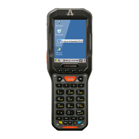
Turn Your Device On 3.5. If you apply the power to your device, it turns on by itself. Do NOT press any keys or interrupt while turning on process. When the process is complete, the Desktop appears, and the terminal is ready for use. Desktop 3.6. -
Page 19: Using The Stylus
Shows phone signal mode Shows the volume Indicates the Battery Control Panel (CPL) Indicates Clock & Alarm CPL zoom in/ out Access the Bluetooth radio Left and right arrows are used to scroll through additional icons Icon Meaning Indicates AC connection mode Indicates WAN (Phone) connection mode Indicates Sound connection mode Indicates LAN / Bluetooth mode... -
Page 20: Pop-Up Menus
4. Get to Know Your Device Feature of Your Device 4.1. The following list outlines a few of the feature included in your device. PM450 Handy Terminal 4.2. Operating Systems: Microsoft Windows Embedded Handheld 6.5 Pro Micro Processor: Cortex-A8 1GHz ... -
Page 21: Front Panel Layout
GPRS/EDGE : Quad band, 850/900/1800/1900MHz UMTS/HSPA: Five band, 800/850/900/1900/2100MHz GPS: Standalone and Assisted GPS Front Panel Layout 4.3. Touch screen display Scan key Keyboard (56-key Keyboard Alpha-numeric) (32-key Numeric) LED Indicator Shows the information needed to operate your device as follows: Note: The LED is user-programmable. -
Page 22: Display Backlight
Side and Bottom Left / Right Light at the side and bottom of the terminal when a scan fails Blue Light at the side and bottom of the terminal when a scan pass. Keypad 34 numeric keypad (including side scan power button). 57 Alpha-Numeric keypad (including side scan, power button). -
Page 23: Keypad Backlight
☞ NOTE: Using the backlight option while on battery power substantially reduces battery life. You may make the same changes when on external power by tapping the External tab. Keypad Backlight 4.5. To turn on the keypad backlight, check the checkbox. The duration of backlight of keypad synchronizes with LCD backlight’s. - Page 24 Clean the touch panel thoroughly with a clean, non-abrasive, lint-free cloth, Make sure nothing is on the touch panel. Blue tag with backing film: Peel off this mask before application. Align the exposed edge of the screen protector along the left edge of the touch panel. Make sure that it lies flush with edges of the touch panel.
- Page 25 6. Press gently but firmly. Use the card a necessary to smooth out any air pockets or bumps after allocation Press the Power key to weak the terminal and check the touch panel with the stylus.
-
Page 26: Back Panel Layout
Verify that the screen accepts input from the stylus as usual. If not, re-apply the screen protector. Press the Power key to put the terminal back in suspend mode. 10. Clean the surface of the screen protector with a clean, non-abrasive, lint-free cloth. 11. -
Page 27: Left Side Panel Layout
Wrist Lanyard The HANDY TERMINAL comes with Wrist Lanyard. You can attach it to the device. Hand strap The HANDY TERMINAL comes with Hand strap. You can attach it to the device. Finger Saddle This is a slightly depressed and angled area of the back housing that is designed to cradle or “saddle”... -
Page 28: Installing Memory Cards
Side Button You can using the scan using the Scan button. Installing Memory Cards 4.10. The HANDY TERMINAL supports Micro Secure Digital (SD) memory cards up to 32GB. Sandisk, Kingstone and ATP micro SD recommended To access the Micro SD card slot and insert the card, proceed as follows: 1. -
Page 29: Top Panel Layout
Side Button You can use the Programs Buttons option in the Control Panel to change the functionality of the side buttons. Scan function is assigned by default (Scan button). EarJack 3.5pi 4pole Jack. This connector supports Ear-Mic headset Top Panel Layout 4.12. -
Page 30: Peripherals And Accessories
HandyLink Connector The HandyLink mechanical connector is designed to work exclusively with HANDY TERMINAL peripherals and cables. This connector powers the terminal, charges the main battery, and facilitates communication. This connector supports High speed USB 2.0 communication (up to 480 Mbps) Through this connector, you can communicate with a host workstation via Microsoft ActiveSync;... -
Page 31: Li-Ion Battery Packs
Ethernet port. For more information, see Single Slot cradle/Single Ethernet cradle Device on paragraph 12. Li-ion Battery Packs 4.15. The Li-ion battery pack provides the main power supply for the terminal. Battery Power 4.16. The intelligent battery technology inside the terminal features of battery power: •... -
Page 32: Managing Main Battery Power
Main battery pack Charging Options When the battery is installed in the terminal, you can use any of the peripherals listed below to charge the battery. • AC Power Supply to DC Jack Port direct. • Single slot docking cradle/Single slot Ethernet cradle •... -
Page 33: Resetting The Terminal
☞ Start -> Settings -> System -> Power NOTE: You can also check battery power by tapping Resetting the Terminal 4.19. There are three types of system resets: a Soft Reset, a Hard Reset, or a Factory Reset. The soft and hard resets preserve all data stored in the file system. -
Page 34: Suspend Mode
To perform a Hard Reset if the terminal has stopped responding, press and hold the Power button for 8 seconds until the terminal starts to re-boot. Factory Reset CAUTION: To prevent data loss, back up all user data to an SD card or external memory device before performing an upgrade or factory reset. -
Page 35: Pm450 Technical Specifications
PM450 Technical Specifications 4.23. Model PM450 Windows Embedded CE 6.0 Professional Operating System Windows Embedded Handheld 6.5 Professional Application Software Tools and Demos Processor Cortex-A8 1GHz Memory 512MB RAM X 1GB Flash Storage Expansion User accessible Micro SD memory card slot... -
Page 36: Using The Keypad
High impact resistant PC/ABS housings Construction Magnesium alloy internal chassis with component shock mounts Drop 2.0m multiple drops to concrete, MIL-STD-810G Tumble 600 tumble at 1.0m Air: ± 15kV Direct: ± 8kV Environmental Independently certified to meet IP65 standards for moisture and particle resistance Dimensions H;... -
Page 37: Basic Keys
Basic Keys 5.3. Name Function BLUE Modifies the next key pressed to type specific functions. Yellow Toggles the keypad between alpha (upper and lowercase) and numeric modes. (Numeric Key) Indicator changes accordingly on the command bar. Yellow Toggles the keypad between normal and ctrl modes. Indicator changes accordingly (Alpha-Numeric on the command bar. -
Page 38: Normal/Ctrl Modes Of Numeric Keypad
Numeric mode. Normal/Ctrl Modes of Numeric Keypad 5.5. The keypad defaults to normal mode. Use the YELLOW key to toggle between normal and ctrl modes. Pressing the YELLOW key once locks the keypad in normal mode, ctrl mode. The command bar on the screen displays an icon that indicates the normal/ctrl status of the keypad. Icon Keypad Status Normal mode. - Page 39 BLUE + F11 BLUE + F12 BLUE + 1 Volume Up BLUE + 4 Volume Down BLUE + 3 Backlight Up BLUE + 6 Backlight Down BLUE + 5 Page Up BLUE + 0 Page Down BLUE + 1 Home BLUE + 9 BLUE + ENT BLUE + TAB...
-
Page 40: Program Buttons
BLUE + A Volume Up BLUE + F Volume Down BLUE + E Backlight Up BLUE + J Backlight Down BLUE + H Page Up BLUE + R Page Down BLUE + L Home BLUE + N BLUE + SP Windows Manu BLUE + SHIFT Align the screen(Press ESC to exit) -
Page 41: Using The Image Engine
No Action No Action No Action No Action No Action No Action No Action No Action No Action No Action No Action No Action (Alpha-Numeric only) No Action (Alpha-Numeric only) No Action (Alpha-Numeric only) No Action (Alpha-Numeric only) 6. Using the Image Engine Overview 6.1. -
Page 42: Available Image Engines
☞ NOTE: It may not read the barcode if it is blue on white background. Try again after changing angle or adjusting the brightness of the surrounding. ☞ NOTE: It may not read the barcode if it is black on silver background. Try again after changing angle or adjusting the brightness of the surrounding. -
Page 43: Supported Bar Code Symbologies
☞ NOTE: Test Condition: Room Temperature (Approx. 23°C), 0 Lux. New picture :N560X-IM RevC.pdf base. Supported Bar Code Symbologies 6.4. Symbology Type Symbology Name UPC,/EAN/JAN ISBT 128, 1D Symbologies GS1 DataBar, GS1-128, Code 11, Matrix 2 of 5, Code 39, MSI, Code 128, Straight 2 of 5,... -
Page 44: Activating The Engine
Codabar, Trioptic Code Interleaved 2 of 5, Aztec Code 2D Symbologies Codablock F Data Matrix MaxiCode MicroPDF417 PDF417 QR Code and Micro QR Code Han Xin OCR-A OCR Option OCR-B Australian Post Postal Codes British Post Canadian Post China Post Japanese Post Korea Post Netherlands(KIX) Pst... -
Page 45: Sample Bar Codes
4. Center the aimer crosshair over the bar code. The aiming beam should be oriented in line with the bar code to achieve optimal decoding; Omni-Directional Scanning Positions on paragraph 6.10. 5. When the bar code is successfully decoded, the decode LED lights green and the terminal beeps. Sample Bar Codes 6.9. -
Page 46: Capturing Images (It5300Sr Engine Only)
☞ New picture :N560X-IM RevC.pdf base. NOTE: ☞ NOTE: To achieve the best read, the aiming beam should be centered horizontally across the bar code. The aiming pattern is smaller when the terminal is held closer to the code and larger when the terminal is held farther from the code. - Page 47 ☞ New picture :SE965HP – Integration Guide – Jan 2013 – 15156605a.pdf base. NOTE:...
-
Page 48: Activating The Engine
Supported Bar Code Symbologies 7.4. Symbology Type Symbology Name UPC A CODE 93 1D Symbologies UPC E CODE 128 UPC E1 ISBT 128 EAN 8 TRIOPTIC CODE 39 EAN 13 INTERLEAVED 2 OF 5 BOOKLAND EAN DISCRETE 2 OF 5 GS1 128(EAN 128) CODABAR GS1_DATABAR 14... -
Page 49: Scanning Positions
Scanning Positions 7.9. The aiming beam must be aimed across the entire bar code to provide you with the best scanning performance. The aiming pattern is smaller when the terminal is held closer to the code and larger when the terminal is held farther from the code. Symbologies with smaller bars or elements (mil size) should be read closer to the unit whereas larger bars or elements (mil size) should be read farther from the unit. -
Page 50: Using Control Panel
Menu Item Sub Item This item … Enables and disables the audio notification for decode/data Beep reception. There is one sound for success and another sound for an error. Notification Enables and disables LED notification for decode/data reception. Vibrator Enables and disables Vibrator notification for decode/data reception. Specifies the method to use when sending the decoded message to the foreground application Keyboard... -
Page 51: Device Id
Device ID 9.1.2. Your device uses this information to identify itself to other computers. Terminal Serial Number will be in Device Name section by default. You can modify it Copyrights 9.1.3. Portions of this software are based on NCSA Mosaic. Power properties 9.2. -
Page 52: Advanced Tab
Advanced tab 9.2.2. To adjust power management settings, 1. Set idle time when on battery power before device suspends. 2. Set idle time when on external power before device suspends. 3. To exit, press OK from the command bar, or press the < ENT > key on the keypad. ☞... -
Page 53: Key Define Tab
Default – button will be assigned default function. No function – button does not have any functions. Scan key – button is used as Scan key. Application – click on Open button and select application to bind with this key. To exit, press OK from the command bar, or press the <... -
Page 54: Program Buttons Tab
Battery power Tab 9.4.1. Modify display backlight settings when device runs on batteries. Set display brightness level Set backlight timeout time. Available options: 10 sec (by default) 30 sec 1 min 2 min 3 min 4 min 5 min ... -
Page 55: Scanner Settings
Tap the Scanwedge icon in the System Tray to open the menu shown in image on the right and select Settings to open the Scanner Settings applet or Start > Settings > System > Scanner Settings... -
Page 56: Scanner Settings Applet
Scanner Settings Applet 9.5.1. Section Option Description Specifies the trigger time out in seconds. If a barcode is not Trigger timeout (sec) decoded within the specified timeout, the default Notifier indicates that decoding is failed Enable Auto Scan with specified Enable Auto Scan interval. - Page 57 Enable to transmit predefined Transmit Barcode ID barcode ID in Detail tab Enter Prefix to be sent prior to Prefix the decoded/received data. Enter Suffix to be sent after the Suffix decoded/received data Translate designated text in the Translate Advanced settings for Scan Data to another text Wedge string modification...
-
Page 58: 10. Communication
10. Communication Communication Options 10.1. Handy Terminal offers several communication options including Microsoft ActiveSync and wireless radios. HandyLink Connector (Wired Communication) The mechanical connector on the bottom panel connects the terminal to various Handy Terminal communication peripherals that connect to a host workstation via USB (1.1 or higher), thus enabling ActiveSync communication. -
Page 59: Connecting The Usb Activesync Cable
ActiveSync Communication 10.4. To synchronize, ActiveSync 4.1 or higher must be installed and configured for the appropriate communication type on the host workstation and the Handy Terminal. Handy Terminals ship with ActiveSync already installed. Therefore, if ActiveSync is already installed on the host workstation, you just need to connect the Handy Terminal to the host workstation (via Handy Terminal peripheral) to initiate communication. -
Page 60: Hardware Requirements For Setup
• ActiveSync v4.1 or higher (for Windows XP), Windows Mobile Device Center (for Vista and Windows 7) installed on the host workstation • Windows XP, Windows Vista, Windows 7 computer. Software Requirements for Communication 10.7. To sync successfully, ActiveSync must be configured for the same communication type on both the host workstation and the Handy Terminal. -
Page 61: Synchronizing With The Host Workstation
The Mobile Device folder opens in Windows Explorer. The Handy Terminal is now treated as a mass storage device, and transferring files is as simple as dragging and dropping or copying and pasting as you would for moving files between folders on your hard drive. -
Page 62: Adding Programs Via Activesync
3. Phone (WWAN configuration): 3G WWAN HSPA Module 4. GPS: Module inherent to HSPA Module ☞ NOTE: PM450 does not provide all Bluetooth profiles. Connecting the Terminal to a Wireless Network 10.14. You connect the terminal to a wireless network through the on-board radio (802.11b/g/n Bluetooth and/or Phone). -
Page 63: Wlan (802.11B/G/N Radio)
☞ NOTE: 802.11 a/b/g/n radio module is off by default, in order to avoid wasting energy, you can switch it off using the Wireless Communications applet ☞ NOTE: Suspending the terminal powers off the 802.11 b/g/n radio and drops the radio connection. When the terminal resumes, depending on the radio power mode and security protocol selected, it may take up to 30 seconds for the 802.11 b/g/n radio drivers to re-associate the radio to the network. -
Page 64: 11. Bluetooth Handler
5. On the terminal, the installer file; e.g., the *.exe file. 6. The installation wizard for the program begins. 7. Follow the directions on the screen to complete installation. 11. Bluetooth Handler Bluetooth wireless technology is a short-range communications technology to connect portable and/or fixed devices while maintaining high levels of security. -
Page 65: Connecting To Other Devices
Setting Up a Bluetooth Printer 11.4. 1. Make sure that the Bluetooth printer is on and activated. 2. If not done so already, turn Bluetooth On (by selecting the vertical arrow on the Command Bar). 3. Tap Scan Device, which runs a Bluetooth Inquiry, then SDP Query. 4. -
Page 66: Front Panel
AVERTISSEMENT : Nous recommandons l'utilisation des périphériques, câbles d'alimentation et les adaptateurs électriques fournis par Pointmobile. L'utilisation de tout autre périphérique, peut causer des dommages non couverts par la garantie. Nous recommandons l'utilisation de batteries Li-Ion approuvées par Pointmobile. L'utilisation de toute autre batterie peut causer des dommages non couverts par la garantie Front Panel 12.4. -
Page 67: Powering The Single Slot Docking Cradle Or Single Slot Ethernet Cradle Device
USB-compliant device to facilitate USB communication to and from the terminal. USB communication occurs through Microsoft ActiveSync (v.4.1 or higher). For more information about ActiveSync setup, see ActiveSync Communication on paragraph 10.4. Ethernet Port (Single Ethernet cradle only) Using an Ethernet cable, you can connect the Single Ethernet cradle to an Ethernet-compliant device to facilitate Ethernet communication to and from the terminal. -
Page 68: Technical Specifications
charging; if it is green, the charge is complete WARNING: Do not short-circuit between each contact of the cradle. It may cause fire. : Provoquer un court-circuit entre les contacts de la station d’accueil, pourrait provoquer un incendie. AVERTISSEMENT Technical Specifications for Cradle 12.8. -
Page 69: Overview
Green: charged Status LED Red: charging Communication MicroUSB connector supports data transmission of up to 480Mbps OR Interface Ethernet 10/100BASE-T(support only PM450-SEC) Agency Approvals UL listed Power Supply TUV licensed Power Supply compliant to FCC part 15, Class B CE Marking (EMC) -
Page 70: 4-Slot Battery Charger
Tous les pièces et parties doivent être sèches avant la connexion à une source d'alimentation externe Front Panel 13.3. Battery connector Charging LED Charging Slots The charger contains four charging slots. Each slot holds one battery. When a battery is placed in a slot, it immediately begins charging and its Status LED lights. -
Page 71: Charging Thebattery
Charging the Battery 13.5. The base powers the terminal and fully charges the battery pack in 4 or 6 hours depending on the battery. As battery packs charge, the charging circuitry follows the two-step charging process (CC-CV) that is recommended for Li-Ion batteries. The process monitors changes in temperature, current, and voltage. -
Page 72: Technical Specifications
Technical Specifications for 4-slot battery charger 13.6. Model 4SBC (4- Slot Battery Charger) Structural Dimensions 256mm(L) x 105mm(W) x 37mm(H) Weight 4- Slot Battery Charger - 434g Material Polycarbonate Color Black Environmental Operating Temperature -20° to 55°C Storage Temperature -25° to +70°C 0~45℃...
Need help?
Do you have a question about the PM450 and is the answer not in the manual?
Questions and answers