
Related Manuals for Windsor 1.005.293.0


Summary of Contents for Windsor 1.005.293.0
- Page 1 Operating instructions (ENG) MODELS: 1.005.293.0 1.005-294.0 Read these instructions before using the machine. 86375030-G 11/25/14...
-
Page 2: Machine Data Label
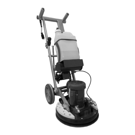
Machine Data Label Overview The Floor Machine is a mains powered, portable floor scrubber intended for commercial use. The appliance can be fitted with a variety of pads to perform various floor care functions. Warranty Registration Thank you for choosing our product. Warranty registration is quick and easy. Your registration will allow us to serve you better over the lifetime of the product. -
Page 3: Table Of Contents
Table of Contents Parts Machine Data Label ......2 Overview ........2 Bottle Holder . -
Page 4: How To Use This Manual
How To Use This Manual This manual contains the following sections: • How to Use This Manual The SAFETY section contains important information regarding hazardous or unsafe practices of the • Safety machine. Levels of hazards are identified that could •... -
Page 5: Safety
Safety IMPORTANT SAFETY INSTRUCTIONS When using this machine, basic precaution must always be followed, including the following: READ ALL INSTRUCTIONS BEFORE USING THIS MACHINE. To reduce the risk of fire, electric shock, or injury: Use only indoors. Do not use outdoors or expose to rain. Use only as described in this manual. - Page 6 Safety IMPORTANTES MESURES DE SÉCURITÉ L'utilisation d'un appareil électrique demande certaines précautions: LIRE TOUTES LES INSTRUCTIONS AVANT DE FAIRE FONCTIONNER (CET APPAREIL). Pour réduire les risques d'incendie, de chocs électriques, ou de blessures. N'utiliser cette machine qu'en intérieur. Ne jamais l'utiliser à l'extérieur ou dans la pluie. N'utiliser cette machine que comme décrit dans le présent manuel.
-
Page 7: Hazard Intensity Level
Safety The following symbols are used throughout this guide as indicated in their descriptions HAZARD INTENSITY LEVEL There are three levels of hazard intensity identified by signal words -WARNING and CAUTION and FOR SAFETY. The level of hazard intensity is determined by the following definitions: WARNING - Hazards or unsafe practices which COULD result in severe personal injury or death. - Page 8 Safety Les symboles ci-dessous sont utilisés à travers ce manuel comme illustré dans leurs descriptions : DEGRÉS DE RISQUES EN CAS DE DANGER Il existe trois degrés de risques identifiés par les termes signalétiques -AVERTISSEMENT et ATTENTION et POUR VOTRE SÉCURITÉ. Le degré de risque est défini de la manière suivante : Dangers ou méthodes dangereuses qui POURRAIENT provoquer de graves blessures ou entraîner la mort.
- Page 9 Safety GROUNDING INSTRUCTIONS 120V Grounding Pin THIS PRODUCT IS FOR COMMERCIAL USE ONLY GROUNDING CONNECTION ELECTRICAL: USING AN ADAPTOR Grounded Grounded Outlet Box In the USA this machine operates on a 15 amp nominal Adaptor Outlet 120V, 60 hz, A.C. power circuit. The amp, hertz, and FIGURE A voltage are listed on the data label found on each machine.
-
Page 10: Safety Labels
Safety Labels SAFETY LABEL LOCATION These drawings indicate the location of safety labels on the Machine. If, at any time, the labels become illegible contact your authorized representative for prompt replacement. EMPLACEMENT DE L'ÉTIQUETTE DE SÉCURITÉ REMARQUE : Ces dessins indiquent l'emplacement des étiquettes de sécurité sur la machine. Si, à tout moment,les étiquettes deviennent illisibles, contactez votre représentant autorisé... - Page 11 Technical Details ITEM MEASURE Motor 1HP, 100-240V/50-60Hz, 6 amps (50Hz)/11amp (60Hz) 1725 (60Hz)/1400 (50Hz) Base diameter 17“/43 cm Orbital diameter 3/8” (9.5 mm) Weight 82 Lbs./37 kg Basic /102 Lbs./46 kg Deluxe Height 48” (122 cm) Compact size for transport and storage 30”...
- Page 12 Notes 86375030 Manual...
-
Page 13: Operation
Operation Unpacking and Initial Operations Open the shipping box on both sides, remove the packaging material and roll the machine out of the box. Put the handle in an upright position. Lift the round screw knobs up and over the top latch bracket and turn clockwise to lock properly. -
Page 14: Pre-Run Inspection
Operation Pre-Run Inspection Before each use inspect the accessory such as the pad driver for cracks, tears or excess wear. If the machine or accessory is dropped, inspect for damage to install an undamaged accessory. Repair the damaged machine before the next applica- tion. - Page 15 Operation Make sure you put the wheels back on the ground in time, to avoid the base from falling on the ground. This might cause damage! Assurez-vous de toujours garder les roues arrière sur le sol, pour éviter que la base ne tombe sur le sol. Cela pourrait causer des dommages! Now you are able to control the base and place it carefully on the pad...
-
Page 16: Pump
Operation Pump For priming the pump system for the first time, put the yellow lever, which is located on the left side of the machine in a vertical position Hold down the black spray button on the right end of the handle for about 30 seconds until the pump is working at its full capacity. - Page 17 Operation Set the handle position to the desired height by pulling and releasing the black knob with the left hand. While holding the black knob out, raise or lower the handle frame with your right hand. To fix the handle frame into place, release the black knob so that it locks firmly into one of the holes provided.
-
Page 18: Process Of Cleaning
Operation Process of Cleaning For effective floor cleaning, move the machine forward and backwards. We recommend you to wet the floor as you move the machine forward, releasing the spray button when you move the machine backwards. To increase the pressure and cleaning effect on certain floors like tile and grout, you can lift the machine frame up, raising the wheels off the ground. -
Page 19: Storage
Operation Storage To store the base in the upright position, press down the handle frame with the right hand and lift up the base with the left hand by grabbing the base handle. The machine base should now rest on the black bumper foot, located at the back of the bumper. -
Page 20: Lifting And Carrying
Operation Lifting and Carrying If you do not have a ramp, we recommend that you lift the machine at all times with two people in and out of a vehicle. Put the firmly locked handle into a lowered position. Make sure that the machine base rests on a pad, so that the Velcro surface of the driver plate does not get damaged or hooked onto a carpeted surface. -
Page 21: Weight Kit Installation
Operation Weight Kit Installation The total weight of the weight kit is 40 lbs. Put the weights on top of the white mounting plates located on the sides of the machine base. Put the four screws into the holes provided on the weight plates and fasten by turning clockwise. -
Page 22: Brush Installation
Operation Brush Installation Put the machine base in an upright position, sitting on the foot of the bumper. Remove the driver plate by removing the four countersink screws in the center of the plate using an electric screw- driver. It is important to only use a Number 3 Phillips head screwdriver bit. Smaller bit sizes can damage the screw heads and leave sharp edges, which can tear or snag the pads. -
Page 23: Attaching And Removing The Driver Plates
Operation Attaching and Removing the Driver Plates Put the machine base in an upright position, sitting on the foot of the bumper. Remove the driver plate by removing the four countersink screws in the center of the plate using an electric screwdriver. It is important to only use a Number 3 Phillips head screwdriver bit as smaller bit sizes can damage the screw heads. -
Page 24: Accessories And Applications
Operation Accessories And Applications Never store the accessories in wet conditions. Keep the accessories away from extreme heat and from chemicals. N'entreposez jamais les accessoires dans des endroits humides. Gardez les accessoires hors de la chaleur extrême et de produits chimiques. Driver Plates Exclusively use designed driver plates only. -
Page 25: Pads
Operation Pads Absorbent Pads The Absorbent pads are made of a cotton-polyester microfiber fabric. Because of their high percentage and quality of cotton, they are highly absorbent and are ideal for cleaning carpets as well as cleaning and drying wet or damp hard floors. -
Page 26: Carpet Pads
Operation Carpet Pads The beige Carpet pads are made of a special blend of fibers and latex that allows the gentle cleaning of heavily soiled short-pile carpets as well as the scrubbing of hard floors. Attach the Carpet pads by centering them onto the driver plate. A Carpet pad, used on both sides, cleans an approximate area of 1000 -2000 sq. -
Page 27: Multi-Purpose Brush
Operation Multi-Purpose Brush The bristles of the brush are made of high quality nylon. This unique brush design is ideal for cleaning tile and grout, concrete, rubber flooring and micro-porous surfaces such as porcelain and safety tiles, but can also be used for any other hard surfaces. -
Page 28: Application On Different Floor Types
Operation Application on different Floor Types Carpet Cleaning Vacuum the carpet thoroughly before cleaning. Large dirt particles are removed, allowing the application to be more effective. Depending on the level of soil and the nature of the carpet, select a suitable textile cleaning pad. Absorbent pads are suitable for all types of carpets, while Carpet pads are suitable in particular for the cleaning of heavily soiled commercial carpets. -
Page 29: Maintenance
Maintenance Cleaning the machine: Clean the machine with a soft cloth and a neutral pH cleaner. Cleaning the spray system: Rinse the spray system after each application to prevent clogging of the hoses, filters and the pump system. To rinse the spray system, install a bottle filled with clear water and place a Absorbent pad in front of the spray jets. Rinse the system by holding down the black spray button on the machine’s handle for at least 30 seconds. -
Page 30: Changing The Filters
Maintenance Changing the filters If the spray jets become clogged or should leak, this is a sign that the filters must be changed. To change the filters, open the spray jet caps by turning the caps with a suitable wrench counterclockwise. Fix the spray jet body with a wrench using the other hand for stabilization. -
Page 31: Parts
Parts PARTS 86375030 Manual... -
Page 32: Bottle Holder
Bottle Holder 86375030 Manual... - Page 33 Bottle Holder SERIAL NO. PART NO. DESCRIPTION NOTES FROM 86376430 CAGE ASSY, BOTTLE HOLDER 86376440 SPRING, BOTTLE HOLDER 86376450 DAMPNER, RUBBER 86374720 BOTTLE, CARTRIDGE, 3 GAL 86376460 BOTTLE CAP, ASSY 86377010 SCREW, 1/2-13 X 4.38 HH STL ZNPLT 86377020 WASHER, NYLON, CAGE 86377030 WASHER, 5/8 X 1.75 X .134 FLT ZNPLT 86005790...
-
Page 34: Deck
Deck 86375030 Manual... - Page 35 Deck SERIAL NO. PART NO. DESCRIPTION NOTES FROM 86376500 PLATE, MOTOR MOUNT 86376510 BUMPER SET 86376520 PLATE, BASE, WEIGHT 86376530 HANDLE, BASE 86377290 SCREW, 1/4-20 x 1.5 PHTRH SS 86377070 NUT 1/4-20 X .313 TEE 4 PRONG ZNPLT SCREW, 3/8-16 X .75 HH STL GRD8 YL 86377280 ZNPLTT 86279510...
-
Page 36: Handle - Latch
Handle - Latch 86375030 Manual... - Page 37 Handle - Latch SERIAL NO. PART NO. DESCRIPTION NOTES FROM 86376390 ROD, HANDLE 86376400 LATCH BODY PULL 86376410 LATCH, PULL 86376420 COLLAR, HANDLE LATCH 86376960 SCREW, 1/2-13 X 1.75 HH STL ZNPLT 86376970 WASHER, 1/2 LATCH NYL 86005790 NUT, 1/2-13 HEXTHIN NYLOCK STL ZNPLT 86376920 SCREW, 1/2-13 X 2 HH STL ZNPLT 86377000...
-
Page 38: Handle - Lower
Handle - Lower 86375030 Manual... - Page 39 Handle - Lower SERIAL NO. PART NO. DESCRIPTION NOTES FROM 86376360 WHEEL, 10” 86376370 ROD, WHEEL 86376380 EARS, HANDLE, BASE PLATE 86376940 SCREW 1/2-13 X 3.75 HH STL ZNPLT 86376950 WASHER, NYLON, WHEEL SCREW, 3/8-16 X .75 HH STL GRD8 YL 86377280 ZNPLT 86279510...
-
Page 40: Handle - Middle
Handle - Middle 86375030 Manual... - Page 41 Handle - Middle SERIAL NO. PART NO. DESCRIPTION NOTES FROM 86376280 HINGE, HANDLE 86376350 SCREW, 5/16-24 X 1/2",HHMS, STL, ZNPLT 86376290 LATCH, LOWER ASM, HANDLE 86376870 SCREW, 10-32 X .25 SCHCS STL ZNPLT 86376890 SCREW, 1/2-13 X 2.38 HH STL ZNPLT 86376900 WASHER, NYLON 86005790...
-
Page 42: Handle - Upper
Handle - Upper 86375030 Manual... - Page 43 Handle - Upper SERIAL NO. PART NO. DESCRIPTION NOTES FROM 86376150 HANDLE ASM, UPPER, W/ELEC BOX 86377370 HARNESS, MAIN HANDLE NOT SHOWN 86375130 SWITCH, DP, 2POS, ROCKER SPR 86376250 HARNESS, SPRAYER SWITCH NOT SHOWN 86375120 SWITCH, DP POS, ROCKER 86376260 HARNESS, ON/OFF SWITCH NOT SHOWN 86375140...
-
Page 44: Motor
Motor 86375030 Manual... - Page 45 Motor SERIAL NO. PART NO. DESCRIPTION NOTES FROM 86377400 SCREW, 10-32 X .25 SLTD HH STL ZNPLT 86377410 COVER, FAN MOTOR 86377420 FAN, MOTOR 86377430 NUT, 3/4 CONDUIT 86377440 SCREW, MOTOR LID 86377450 CORD, BLUE PLUG, 100-120V NOT SHOWN 86377460 CORD, BLACK PLUG, 100-120V NOT SHOWN 86376540...
-
Page 46: Nozzle
Nozzle 86375030 Manual... - Page 47 Nozzle SERIAL NO. PART NO. DESCRIPTION NOTES FROM 86376750 FITTING, TEE, SPRAY NOZZLES 86376760 FITTING, 90, SPRAY NOZZLES 86376770 HOSE, SPRAY NOZZLES 86376780 HOSE, SPRAY NOZZLES CAGE 86376790 PLATE, ANGLE, NOZZLE BASE 86376800 PLATE, ANGLE, NOZZLE 86376810 COUPLER, FILTER 86375100 STRAINER, CHECK VALVE 86376820 NOZZLE, SPRAYER...
-
Page 48: Pad
86375030 Manual... - Page 49 SERIAL NO. PART NO. DESCRIPTION NOTES FROM 86376570 DRIVER, DISK, 15” 86376580 DRIVER, VELCRO PLATE, 15” 86397750 ASSY, COUNTERWEIGHT, 17 DISK INCLUDES #9 86377330 SHAFT SUPPORT 86377160 SCREW, 1/4-20 X .75 PHFLHMS SS 86377170 SCREW, 1/4-20 X 1 PHFLH SS 86377070 NUT 1/4-20 X .313 TEE 4 PRONG ZNPLT 86377470...
-
Page 50: Solution
Solution 86375030 Manual... - Page 51 Solution SERIAL NO. PART NO. DESCRIPTION NOTES FROM 86376610 PUMP, 90PSI, 120V 86376620 VALVE, FLOW CONTROL, 3-WAY 86376630 COUPLER, QD, FLOW CONTROL 86376640 NIPPLE, 1/4”, HEX 86376650 COUPLER, FLOW CONTROL 86376660 ELBOW, 1/4”, 90 86377180 WASHER, 1/2 X .75 DSP ZNPLT 86376670 FITTING, ELBOW, 1/4”, 90 86376680...
-
Page 52: Wiring Diagram
Wiring Diagram ON/OFF SWITCH SPRAY SWITCH 1 (BLK) 2 (WHT) 1 (BLK) 2 (WHT) Power Cord from Wall Circuit Breaker Ground Terminal Strip inside handle wiring box 4 (RED) 1 (BLK) Ground 3 (BLU) 2 (WHT) Ground 5(YLW) No Connection (Insulated) 6 (BRN) No Connection (Insulated) Ground Motor Wiring Box... -
Page 53: Suggested Spare Parts
Accessories SERIAL NO. PART NO. DESCRIPTION NOTES FROM 86374640 PAD, ABSORBENT, 21" 86374690 REPLACEMENT DRIVER PLATE PACK 86374660 PAD, CARPET, 19" 86374700 ASSY, GLIDER SET 86374710 ASSY, WEIGHT KIT 86374680 BRUSH, SCRUB 86374670 PAD, STRIPPING, CHEMICAL FREE, 18" 86374720 BOTTLE CARTRIDGE, 2.5 GAL Suggested Spare Parts SERIAL NO.
Need help?
Do you have a question about the 1.005.293.0 and is the answer not in the manual?
Questions and answers