Table of Contents
Advertisement
Advertisement
Table of Contents

Subscribe to Our Youtube Channel
Related Manuals for Progear Fitness Air Elliptical


Summary of Contents for Progear Fitness Air Elliptical
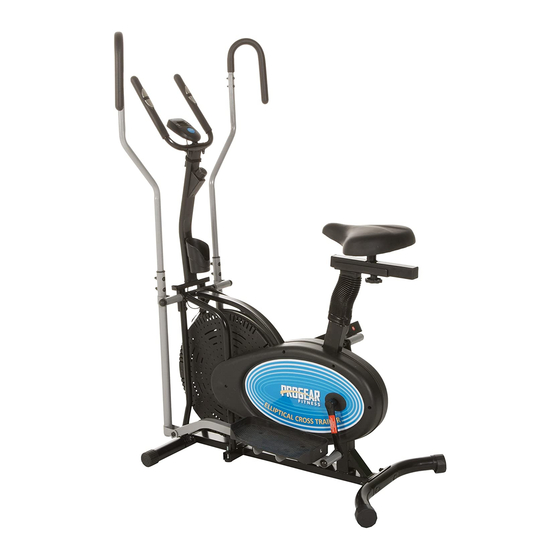
- Page 1 AIR ELLIPTICAL IMPORTANT: Read all instructions carefully before using this product. Retain this owner’s manual for future reference. The specifications of this product may vary from this photo and, subject to change without notice. Item #1308 OWNER’S MANUAL...
-
Page 2: Table Of Contents
TABLE OF CONTENTS SERVICE ------------------------------------------------------------------------------ 2 LABEL PLACEMENT --------------------------------------------------------------- 3 IMPORTANT SAFETY INSTRUCTIONS -------------------------------------- 4 OVERVIEW DRAWING ------------------------------------------------------------ 5 PARTS LIST -------------------------------------------------------------------------- 6 HARDWARE & TOOLS PACK --------------------------------------------------- 8 ASSEMBLY --------------------------------------------------------------------------- 9 COMPUTER -------------------------------------------------------------------------- 18 TENSION ADJUSTMENT --------------------------------------------------------- 19 LEVEL ADJUSTMENTS ----------------------------------------------------------- 20 HOW TO USE U SHAPE GRAB BAR ------------------------------------------ 21 MAINTENANCE ---------------------------------------------------------------------- 22 TROUBLESHOOTING ------------------------------------------------------------- 23... -
Page 3: Service
SERVICE IMPORTANT: FOR NORTH AMERICA ONLY To request product service and order replacement parts, please call our customer service department at: 1-866-924-1688 Monday through Friday, 8:00 AM-5:00 PM Pacific Standard Time, service@paradigmhw.com or email us at: Please visit our website at www.paradigmhw.com. Please have the following information ready when requesting for service: Your name Phone number... -
Page 4: Label Placement
LABEL PLACEMENT... -
Page 5: Important Safety Instructions
IMPORTANT SAFETY INSTRUCTIONS Basic precautions should always be followed, including the following safety instructions when using this equipment. Read all instructions before using this equipment. 1. Before exercising and to avoid injuring your muscles, it is highly recommended that you perform warm-up exercises for each muscle group. Please refer to Warm Up section of the Owner’s Manual. -
Page 6: Overview Drawing
OVERVIEW DRAWING... -
Page 7: Parts List
PARTS LIST Description Qty No. Description Right U Shape Grab Bar 1 028 Nylon Nut for Right Crank 1/2” Ø25x1.8 002 Right Handrail Arm Ø25x1.8 1 029 Computer M1202 U-Shaped Grab Bar Foam Grip Hand Pulse Handlebar End Cap 2 030 Ø24xØ34x410 Ø25x1.5 Handrail Arm Plastic Bushing... - Page 8 PARTS LIST Description Qty No. Description 056 Cap Nut M10 4 086 Screw ST4.2x20 057 Adjustable Leveler M8x45 2 087 Nylon Nut for Left Crank 1/2” 058 Nut M8 2 088 Nut Cap S16 059 Mainframe 1 089 Small Magnet Ø15x7 060 Rotation Rod Ø15.8x376 1 090 Left Handrail Arm Ø25x1.8 061 Rear Stabilizer End Cap Ø50...
-
Page 9: Hardware & Tools Pack
HARDWARE & TOOLS PACK... -
Page 10: Assembly
ASSEMBLY 52 52 52 52 62 62 56 56 Tool: 55 55 59 59 58 58 56 56 55 55 56 56 57 57 55 55 Open-Ended Flat Wrench 52 52 93 93 52 52 1. Front/Rear Stabilizers and Adjustable Levelers Installation: Step A: Align the Front Stabilizer (54) onto the front curve of the Mainframe (59). - Page 11 ASSEMBLY 17 17 Tools: 22 22 S6 Allen Wrench 14 14 S6 Allen Wrench with 88 88 11 11 Phillips Screwdriver 59 59 88 88 22 22 60 60 77 77 76 76 88 88 14 14 Open-Ended Flat Wrench 11 11 88 88 2.
- Page 12 ASSEMBLY Tools: 97 97 Open-Ended Flat Wrench 87 87 S10 Allen Wrench Important: 27 27 Installing right bolt into right crank can only be done by turning right (clockwise). Important: Installing left bolt into left 75 75 crank can only be done by turning left R for right bolt (counterclockwise).
- Page 13 ASSEMBLY Hardware: Step F (88) Nut Cap 4 PCS Step I Step J (21) Right Bolt for Right Crank 1 PC (22) Wave Washer 2 PCS (27) Spring Washer 2 PCS (28) Nylon Nut for Right Crank 1 PC (64) Left Bolt for Left Crank 1 PC (87) Nylon Nut for Left Crank 1 PC...
- Page 14 ASSEMBLY Tool: S6 Allen Wrench with Phillips Screwdriver Open-Ended Flat Wrench 4. Hand Pulse Handlebar Support Frame, Tension Control Knob, Bottle Holder, and Hand Pulse Handlebar Installation: Step L: Attach the Hand Pulse Handlebar Support Frame (41) onto the Mainframe (59) with four Bolts (47), four Spring Washers (36), and four Washers (24).
- Page 15 ASSEMBLY Step P: Install the Tension Control Knob (37) by inserting the tab into a square hole on the Hand Pulse Handlebar Support Frame (41) and push down on the knob slightly in order to align the opening with the bolt hole. Using the screwdriver, tighten the Bolt (38) until firm.
- Page 16 ASSEMBLY 20 20 20 20 Tools: S6 Allen Wrench Open-Ended Flat Wrench 18 18 76 76 25 25 23 23 14 14 14 14 5. Right and Left Foot Pedals Installation: Step S: Attach two Foot Pedal Support Brackets (18) onto both the Right/Left Foot Bars (17, 76) with four Bolts (23) and the other ends with four Washers (24) and four Nylon Nuts (25).
- Page 17 ASSEMBLY Tools: S6 Allen Wrench Open-Ended Flat Wrench 6. Left/Right U Shape Grab Bars, Left/Right Handrail Arms, and Computer Installation: Step V: Insert the Left U Shape Grab Bar (104) into the Left Handrail Arm (90) and secure with two Bolts (103), two Conical Washers (102), and two Big Curve Washers (101), and two Cap Nuts (100).
- Page 18 ASSEMBLY 25 25 Tool: Open-Ended Flat Wrench 59 59 7. Seat Cushion, Seat Sliding Tube, Seat Post, and Seat Post Plastic Tube Installation: Step Z: Remove three Nylon Nuts (25) and three Big Washers (115) from underside of the Seat Cushion (114). Using the flat wrench to remove the nylon nuts. Step Z-1: Guide bolts on underside of the Seat Cushion (114) through holes on top of the Seat Sliding Tube (112), attach with three removed Nylon Nuts (25) and Big Washers (115).
-
Page 19: Computer
COMPUTER SPECIFICATIONS: TIME ---------------------------------------------------- 00:00-99:59 MIN: SEC SPEED ------------------------------------------------- 0.0-999.9 MPH DISTANCE -------------------------------------------- 0.00-99.99 MILE CALORIE ---------------------------------------------- 0.0-999.9 KCAL PULSE ------------------------------------------------- 40-200 BPM USING YOUR COMPUTER The computer can be activated by pressing the MODE button or by pedaling. If you leave the equipment idle for 4 minutes, the power will turn off automatically. -
Page 20: Tension Adjustment
TENSION ADJUSTMENT Adjusting the Tension Control Knob To increase the tension, turn the tension control knob in a clockwise direction. To decrease the tension, turn the tension control knob in a counterclockwise direction. Tension Control Knob After prolong use of the elliptical trainer, the strap will begin to stretch out and it will become necessary to tighten the strap for optimum performance. -
Page 21: Level Adjustments
LEVEL ADJUSTMENTS Adjusting the Rear Stabilizer End Cap or Adjustable Leveler The Elliptical has to be set up on a flat surface. Otherwise, shaking or wobble might occur during the workout. Please use the following Adjustable Leveler two methods to adjust the Elliptical Level. -
Page 22: How To Use U Shape Grab Bar
U Shape Grab Bar U Shape Grab Bar This AIR ELLIPTICAL can be used either as an elliptical trainer or an exercise bike. User can choose to stand up when you want to use the elliptical trainer or sit down on the seat when you use the exercise bike. -
Page 23: Maintenance
MAINTENANCE Regular maintenance of your elliptical is necessary to extend the life of your machine and allow it to continue to function properly. lease keep the elliptical, especially the computer console, out of direct sunlight to prevent screen damage or premature wear. Cleaning Keep the machine clean and free of any debris by vacuuming around the moving parts and wiping the machine down with a clean cotton cloth. -
Page 24: Troubleshooting
TROUBLESHOOTING PROBLEM SOLUTION Check that the batteries are inserted properly with the correct polarity (see marking inside the battery compartment). The computer will not power up. Check that the battery springs are in proper contact with batteries. Remove the old batteries and replace with the new batteries. - Page 25 TROUBLESHOOTING PROBLEM SOLUTION Make sure both the Adjustable Levelers (57) The elliptical is not sturdy enough. are touching the ground. Make sure the elliptical is leveled. Please refer to page 20 Undo the buckle of the plastic clip and then pull the top strap on the front of the unit away Tension adjustment doesn't work.
-
Page 26: Warm Up
WARM UP Quadriceps Stretch With one hand against a wall for balance, reach behind you and pull your right foot up. Bring your heel as close to your buttocks as possible. Hold for 15 counts and repeat with left foot up. Inner Thigh Stretch Sit with the soles of your feet together with your knees pointing outward. -
Page 27: Warranty
WARRANTY MANUFACTURER’S LIMITED WARRANTY Paradigm Health & Wellness warrants to the original purchaser that this product is free from defects in material and workmanship when used for the purpose intended, under the conditions that it has be installed and operated in accordance with Paradigm’s Owner’s Manual. Paradigm’s obligation under this warranty applies to the following: COMPONENT LENGTH OF WARRANTY... -
Page 28: Fax Form
FAX FORM Paradigm Health & Wellness, Inc. PARTS REQUEST FAX FORM Please fax this form to (1-626-810-2166) OR YOU CAN EMAIL CUSTOMER SERVICE REQUESTS TO service@paradigmhw.com NAME: _______________________________________________________ ADDRESS: ____________________________________________________ CITY ______________ STATE ______________ ZIP ___________________ TELEPHONE: (Day) _____________________________________________ (Night) ____________________________________________ (Email Address) ____________________________________ SERIAL#: __________________________________________ ITEM/MODEL#: _____________________________________...
Need help?
Do you have a question about the Air Elliptical and is the answer not in the manual?
Questions and answers