Table of Contents
Advertisement
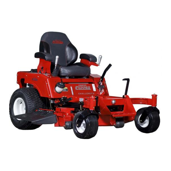
Safety Instructions & Operators Manual
TM
Congratulations for buying a Country Clipper product. Your Country Clipper Zero Turn Radius Riding
Mower was designed and built to provide long and trouble free service. Keep in mind that it, like any
other mechanical device, can be potentially dangerous if used improperly, and hazard control and
accident prevention are dependent upon the awareness, concern, prudence, and proper training of
personnel involved in the operation, transport, maintenance, and storage of the equipment. Study this
manual and pay special attention to the important Safety Precautions on pages 3-5. Following these
instructions will help you continue to enjoy the trouble-free performance expected of the Country Clipper
product.
P-13155
Advertisement
Table of Contents

Subscribe to Our Youtube Channel
Related Manuals for Country Clipper Challanger 510


Summary of Contents for Country Clipper Challanger 510
- Page 1 Study this manual and pay special attention to the important Safety Precautions on pages 3-5. Following these instructions will help you continue to enjoy the trouble-free performance expected of the Country Clipper product.
-
Page 2: Table Of Contents
TABLE OF CONTENTS MODEL NUMBER’S & SERIAL NUMBER’S ................2 SAFETY ............................3 ACCIDENT PATTERNS TO AVOID ....................... 3 SAFETY INSTRUCTIONS AND RECOMMENDATIONS ................3 SAFETY INTERLOCK SYSTEM ........................5 START UP AND OPERATION ....................6 ... -
Page 3: Model Number's & Serial Number's
MODEL NUMBER’S & SERIAL NUMBER’S Date of Purchase: ____________________________________________ Mower Model Number: ____________________________________________ Mower Serial Number: ____________________________________________ Engine Spec Number: ____________________________________________ Hydro Serial Number (RH): ____________________________________________ Hydro Serial Number (LH): ____________________________________________... -
Page 4: Safety
BLADE -- This accident usually OR ARE OTHERWISE ASSOCIATED happens when the operator is clearing with the Country Clipper Zero Turn the discharge chute of grass, (especially Radius Mower should be trained in its when the grass is wet), or when the proper use and warned of its dangers. - Page 5 DO NOT MOVE CONTROL LEVER(S) NEVER REMOVE THE FUEL CAP or from forward position to reverse position add gasoline to a running or hot engine rapidly. The speed and/or direction of that has not been allowed to cool for travel is affected instantly by movement several minutes after running.
-
Page 6: Safety Interlock System
Replace any safety label that is missing or damaged. SAFETY INTERLOCK SYSTEM WEAR PERSONAL PROTECTIVE EQUIPMENT. Eye, ear, feet and head Your Country Clipper Zero Turn Radius Mower protection is recommended. is equipped with switches interlocked for your safety. ONLY USE COUNTRY CLIPPER APPROVED ACCESSORIES. -
Page 7: Start Up And Operation
START UP AND OPERATION IMPORTANT: Before cutting grass, clutch must be broken-in as follows: With engine at CHECKLIST BEFORE OPERATION full RPM engage deck until blades come to full speed and then disengage until 1. Make sure fuel tank is full. Use regular blades come to a complete stop. -
Page 8: Operation Joystick Models
Until the operator is familiar with the Lower Cut Height Adjustment Lever until it Country Clipper Zero Turn Radius rests on Cut Height Stop Pin. NOTE: Mower, he/she should follow these... -
Page 9: Operation Free Wheel
Retaining Slot CAUTION AVOID HILLS AND SLOPES. USE EXTREME CAUTION WHEN MOWING UP OR DOWN SLOPES. NEVER MOW ACROSS THE FACE OF A SLOPE. IF A SLOPE MUST BE ASCENDED, BACK UP THE SLOPE; DRIVE FORWARD WHEN DESCENDING. 13. TO STOP: Move Joystick Control Lever to neutral position and then to the “DOWN”... -
Page 10: Mowing Recommendations
CAUTION NEVER OPERATE MOWER WITHOUT DISCHARGE CHUTE IN PLACE. MOWING RECOMMENDATIONS 1. Keep mower blades sharp. 2. Make sure deck and discharge are clean. CAUTION TURN ENGINE OFF AND WAIT FOR ALL MOVING PARTS TO STOP BEFORE CLEANING DISCHARGE CHUTE. 3. -
Page 11: Maintenance
MAINTENANCE CAUTION BEFORE PERFORMING ANY MAINTENANCE, TURN OFF ENGINE REMOVE KEY AND DISCONNECT SPARK PLUGS. USE EXTREME CARE WHEN WORKING ON MACHINERY. DO NOT WEAR WATCHES OR JEWELRY. DO NOT WEAR LOOSE FITTING CLOTHES, AND OBSERVE ALL COMMON SAFETY PRACTICES WITH TOOLS. MAINTENANCE SCHEDULE Maintenance Service Interval Maintenance Procedure... -
Page 12: Maintenance Instructions
Model Front tires Rear tires included in your Country Clipper Zero 12 psi 12 psi Turn Radius Mower information packet. Models NOTE: Air intake screen must be kept Lug nuts should be torqued to 75 ft/lbs clean. -
Page 13: Joystick Adjustment
JOYSTICK ADJUSTMENT 5. V-BELTS: 1. SETTING TRACKING AND FORWARD SPEED: All belts should be checked every 50 hours. Replace any belts found to be in A. The initial setting is done with the poor condition. All belts are equipped engine TURNED OFF. with spring loaded belt tighteners and do B. - Page 14 H. Loosen the jam nuts on both ends of the left side transmission linkage. One of these is a left-hand thread. Now rotate the linkage rod a couple turns to lengthen it. Hold the joystick control handle firmly in the full forward position. Rotate the left side transmission linkage rod to shorten the linkage until resistance is felt from Outside...
-
Page 15: Hydrostatic Transmissions
Long silver spacer Neutral Cross Bolt Plate Long silver spacer Short gold spacer Neutral Plate Nuts Short gold spacer B. Start the engine. With the joystick still down, position the handle so both wheels are stationary. HYDROSTATIC TRANSMISSIONS C. Tighten the two nuts on the bottom of the neutral plate, being careful not to shift it out of position. -
Page 16: Procedure For Raising And Lowering The Deck For Servicing
6 times. As air is purged from the unit, the filter (use part # H-2567 when the oil level will drop. ordering from Country Clipper).Wipe off the filter base surface, apply a film of B. With the transmission locked and the... - Page 17 (this will lock the cut height adjustment lever into the lowest position). B. Carefully rotate the Deck Belt Tension. Latch to release tension on the Deck LOWERING THE DECK: Belt. Remove the engine to deck Drive belt from the clutch on the engine. Flip A.
- Page 18 MOWER SHOWN IN OPERATING POSITION. Cut Height Adjustment Lever Cut Height Adjustment Foot Deck Flip Front Step Up Front Caster Pivot Grease Zerk Latch Plate Front Caster Wheels positioned out of the way. MOWER SHOWN IN SERVICING POSITION. Hook Keeper Deck Hook Deck raised to service position...
-
Page 19: Securing The Deck Prop
SECURING THE DECK PROP Deck Prop shown in the “Stowed” position. Deck Prop being placed against the Deck lift casting. Deck Prop securely in place against Deck lift casting. -
Page 20: Leveling The Deck
4. Measure from the ground to the front blade tip of each outside blade. These measurements should be within 1/8” of each other. (NOTE: To simplify this measuring, an optional Blade Measuring tool, part Number 629-374A is available from your local “Country Clipper” Dealer) Deck hanger bolt Part # F-1936 1/2"... -
Page 21: Adjusting The Latch Plate
ADJUSTING THE LATCH PLATE 1. Level the deck before proceeding to adjust the latch plate. (Follow instructions on previous page.) Pin the deck in the lowest position before proceeding to adjust the latch plate. 2. Lift up on the hook keeper, while pulling up on the release handle. This will disconnect the rear of the deck. -
Page 22: Trouble Shooting Check List
TROUBLE SHOOTING CHECK LIST ENGINE WON’T TURN OVER: Mower blades engaged ---------------------------------------------------------------- disengage blades Drive not in neutral ---------------------------------------- move Control Lever(s) to neutral position Blown fuse ---------------------------------------------------------------------------------------- replace fuse Dead battery ------------------------------------------------------------------------------ charge or replace Solenoid ---------------------------------------------------------------------------------------- consult dealer Ignition switch --------------------------------------------------------------------------------- consult dealer Starter ------------------------------------------------------------------------------------------- consult dealer ENGINE WILL TURN OVER BUT WON’T START:... - Page 23 ENGINE SOMETIMES SKIPS AT HIGHER SPEEDS: Incorrect Ignition Timing -------------------------------------------------------------------- consult dealer Carburetor maladjusted --------------------------------------------------------------- readjust carburetor Faulty spark plugs ------------------------------------------------------------------------ check spark plug condition and reset gap* Bouncing off seat safety switch ------------------------------------------ slow down on rough terrain ENGINE OVER HEATED: Air intake screen or fins clogged --------------------------------------- clean intake screen and fins Fuel mixture too lean ----------------------------------------------------------------- readjust carburetor* Oil level too low or too high ---------------------------------------------------------------- adjust oil level...
-
Page 24: Belt Routings
BELT ROUTINGS Hydrostatic Transmission Drive Belt (Viewed from ground looking up) Right Hand Hydrostatic Left Hand Hydrostatic Transmission Pulley Transmission Pulley Belt P/N D-3905 Motor Pulley 60” DECK BELT 52” DECK BELT P/N: D-3776-W P/N: D-3872 Clutch Clutch "V" IDLER "V"... -
Page 28: Notes / Service Records
NOTES / SERVICE RECORDS: DATE SERVICE WORK COMPLETED... -
Page 29: Notes / Service Records
NOTES / SERVICE RECORDS: DATE SERVICE WORK COMPLETED... - Page 30 Safety Instructions & Operators Manual Country Clipper Division Shivvers Manufacturing Inc. 613 W. English St. Corydon, IA 50060-0467 Ph. 641-872-2544 Fax. 641-872-1593 P-13155...
Need help?
Do you have a question about the Challanger 510 and is the answer not in the manual?
Questions and answers