Table of Contents
Advertisement
Table of Contents
Main Menu
Safety Instructions & Operators Manual
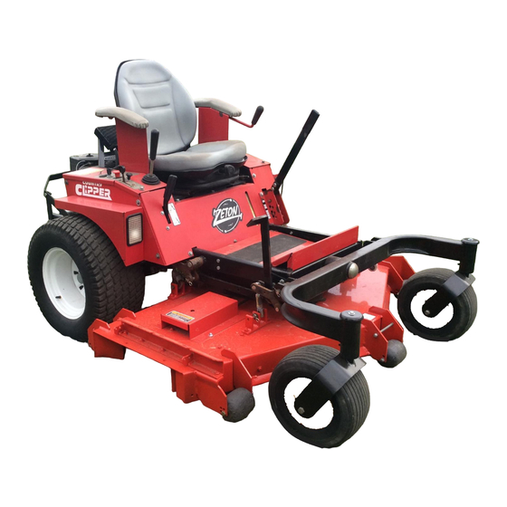
COUNTRY CLIPPER
Congratulations for buying a Country Clipper product. Your Country Clipper Zero
Turning Radius Riding Mower was designed and built to provide long and trouble free
service. Keep in mind that it, like any other mechanical device, can be potentially
dangerous if used improperly, and hazard control and accident prevention are
dependent upon the awareness, concern, prudence, and proper training of personnel
involved in the operation, transport, maintenance, and storage of the equipment. Study
this manual and pay special attention to the important Safety Precautions on pages 4-6.
Following these instructions will help you continue to enjoy the trouble-free performance
expected of the Country Clipper product.
P-11527 (2004)
Copyright, Shivvers Mfg., 2004
Advertisement
Table of Contents

Related Manuals for Country Clipper Zeton


Summary of Contents for Country Clipper Zeton
- Page 1 Safety Instructions & Operators Manual COUNTRY CLIPPER Congratulations for buying a Country Clipper product. Your Country Clipper Zero Turning Radius Riding Mower was designed and built to provide long and trouble free service. Keep in mind that it, like any other mechanical device, can be potentially...
- Page 2 Table of Contents WARRANTY INFORMATION SERIAL NUMBER ____________________________________________________________________ DATE PURCHASED __________________________________________________________________ Condition of Mower (New or Used)________________________________________________________ Hour Meter Reading____________________________________________________________________ SERVICE SCHEDULE Service Performed and Date ______________________________________________ ______________________________________________ ______________________________________________ ______________________________________________ ______________________________________________ ______________________________________________ ______________________________________________ ______________________________________________ ______________________________________________ ______________________________________________ ______________________________________________ ______________________________________________ ______________________________________________ ______________________________________________ ______________________________________________ ______________________________________________ ______________________________________________...
-
Page 3: Table Of Contents
TABLE OF CONTENTS Zeton & Zeton Boss Cover Page I. OWNER INFORMATION Warranty Information ----------------------------------------------------------- 2 II. SAFETY Accident Patterns ----------------------------------------------------------------- 4 Safety Instructions and Recommendation -------------------------------- 4 Safety Interlock Systems ------------------------------------------------------- 6 Operation --------------------------------------------------------------------------- 7 - 8 III. START UP AND OPERATION... -
Page 4: Accident Patterns
BLADE -- This accident usually OR ARE OTHERWISE ASSOCIATED happens when the operator is clearing with the Country Clipper Zero Turning the discharge chute of grass, (especially Radius Mower should be trained in its when the grass is wet), or when the proper use and warned of its dangers. - Page 5 Table of Contents DO NOT MOVE CONTROL LEVER(S) DO NOT SMOKE AROUND THE from forward position to reverse position MOWER or the gasoline storage rapidly. The speed and/or direction of container. Gasoline fumes can easily travel is affected instantly by movement Ignite.
-
Page 6: Safety Interlock Systems
HIGHLY FLAMMABLE. DO NOT SMOKE. SAFETY INTERLOCK SYSTEM ENGINE SHOULD BE OFF AND COOL. USE APPROVED GAS CONTAINER. NEVER FILL Your Country Clipper Zero Turning Radius TANK INDOORS. WIPE UP ANY SPILLS. Mower is equipped with switches interlocked for REPLACE CAP TIGHTLY. - Page 7 RELEASE PARKING BRAKE. Push brake Lever lever down to release. IMPORTANT: Until the operator is familiar with Ignition the Country Clipper Zero Turning Radius Mower, he/she should follow these recommendations: Disengage the mower blades. Go very slowly until thoroughly familiar with the machine.
- Page 8 Table of Contents TWINSTICK STEERING INFORMATION Clean the air intake screen on the DISENGAGE MOWER BLADE CLUTCH by engine if necessary. moving clutch switch to “OFF” position. PULL ENGINE CHOKE CONTROL to full Perform any other maintenance as it position for cold starts.(Choke is not used becomes necessary.
- Page 9 Table of Contents CAUTION B. Disengage the mower blade clutch by moving the clutch to the “OFF” position. C. Set the parking brake. FOR SMOOTH, SAFE OPERATION, MOVE THE CONTROL LEVER(S) IN A GENTLE, D. Slow engine speed with throttle to SLOW MOTION.
-
Page 10: Mowing Recommendations
10 ga Spindle Bearings 25 mm NOTE: Tractor should be matched to deck to insure sufficient power is available for the intended usage. ZETON BOSS (2707 series) uses the 6005M or the 7205M deck ONLY. P-11527 Copyright, Shivvers Mfg., 2004... -
Page 11: Maintenance
Table of Contents MAINTENANCE CAUTION BEFORE PERFORMING ANY MAINTENANCE, TURN OFF ENGINE REMOVE KEY AND DISCONNECT SPARK PLUGS. USE EXTREME CARE WHEN WORKING ON MACHINERY. DO NOT WEAR WATCHES OR JEWELRY. DO NOT WEAR LOOSE FITTING CLOTHES, AND OBSERVE ALL COMMON SAFETY PRACTICES WITH TOOLS. MAINTENANCE SCHEDULE SERVICE WHEN... -
Page 12: Maintenance Instructions
Inflate tires to by the engine manufacturer and the pressures listed below: included in your Country Clipper Zero Turning Radius Mower information Model Front tires Rear tires packet. - Page 13 Table of Contents D. Check balance of blade by positioning the blade on a nail or blade Check the oil level in hydrostatic balance pedestal. Grind the blade on transmission oil reservoir after every 25 the end that is heavier until both sides balance.
- Page 14 Table of Contents TWINSTICK STEERING CONTROL ADJUSTMENT 8. To Adjust Neutral: a. Remove the fender skirts from each 11. Adjusting for Straight Forward side of the machine. Tracking: b. Block up the unit so that the Drive Wheels are off the ground. In a large open area, actuate the control c.
- Page 15 Table of Contents JOYSTICK CONTROL LEVER A. Remove the right hand fender skirt NEUTRAL ADJUSTMENT: exposing the Joystick Control Lever With the engine running, if the machine assembly. travels in either direction when the Joystick Control Lever is in the neutral B.
- Page 16 Table of Contents B. Stop the machine and shut of the engine. R. H. Upper L.H. Upper Linkage C. Slightly loosen the bolt at the lower Linkage Assembly end of the upper linkage assembly Assembly on the side that is slower. Using a 1/8”...
- Page 17 Table of Contents easier if someone stands on the rear PROCEDURE FOR RAISING AND bumper of the tractor). IMPORTANT LOWERING THE DECK FOR NOTE: MAKE SURE THAT THE SERVICING DECK IS LIFTED FAR ENOUGH FOR THE DECK LATCH TO FULLY ENGAGE THE LOCKING PIN (located 14.
-
Page 18: Leveling The Deck
Table of Contents MOWER SHOWN IN SERVICING Deck Latch in locked POSITION. position. Foot Deck in up position Engine to Deck Drive Belt hooked to bolt. LEVELING THE DECK: A. Set the tire pressure on all four tires B. Move the tractor to a hard, level surface (i.e. concrete or blacktop). Place a 2 x 4 board under all four corners of the deck shell, just inside of the anti-scalping wheels. - Page 19 Table of Contents ASSEMBLY / OPERATION SHEET DECK FLIP JACK 1. Turn off lawn mower and set brakes. Remove cut/height adjust pin and lower deck lift handle to lowest position. Reinsert cut/height adjust pin above deck lift handle. 2. .Flip up the foot deck to allow access to the engine to deck drive belt, roll the engine to deck drive belt off the center spindle.
-
Page 20: Trouble Shooting Checklist
Table of Contents TROUBLE SHOOTING CHECK LIST ENGINE WON’T TURN OVER: Mower blades engaged ------------------------------------------------- disengage blades Drive not in neutral --- move Joystick Control Lever to neutral “DOWN” position move Twinstick Control Levers to neutral “OUT” position Blown fuse ------------------------------------------------------------------------ replace fuse Dead battery --------------------------------------------------------------- charge or replace Solenoid ------------------------------------------------------------------------- consult dealer Ignition switch ------------------------------------------------------------------ consult dealer... - Page 21 Table of Contents ENGINE SOMETIMES SKIPS AT HIGHER SPEEDS: Incorrect Ignition Timing ---------------------------------------------------- consult dealer Carburetor maladjusted ----------------------------------------------- readjust carburetor Faulty spark plugs --------------------------------------------------------- check spark plug condition and reset gap* Bouncing off seat safety switch -------------------------- slow down on rough terrain ENGINE OVER HEATED: Air intake screen or fins clogged ------------------------ clean intake screen and fins Fuel mixture too lean ------------------------------------------------- readjust carburetor*...
-
Page 22: Wiring Schematic For Joystick Model
Table of Contents WIRING SCHEMATIC: FOR JOYSTICK MODEL Note: All wire connectors shown at wire side. Black wires = Ground START SWITCH Red wires = Power POSITION CIRCUIT “MAKE Blue wires = Kill Circuit Yellow wires = Start Circuit Green wires = Signal Circuit START B+L+S P-11527... -
Page 23: Wiring Schematic For Twinstick Model
Table of Contents WIRING SCHEMATIC: FOR TWINSTICK MODEL NOTE: ALL WIRE CONNECTORS SHOWN AT WIRE SIDE Black wires = Ground START SWITCH Red wires = Power POSITION CIRCUIT “MAKE Blue wires = Kill Circuit Yellow wires = Start Circuit Green wires = Signal Circuit START B+L+S P-11527... - Page 24 WIRING SCHEMATIC: FOR E.F.I. JOYSTICK MODEL Table of Contents Black wires = Ground START SWITCH Red wires = Power POSITION CIRCUIT “MAKE Blue wires = Kill Circuit Yellow wires = Start Circuit Green wires = Signal Circuit START B+L+S P-11527 Copyright, Shivvers Mfg., 2004...
- Page 25 WIRING SCHEMATIC: FOR E.F.I. TWINSTICK MODEL Table of Contents START SWITCH Black wires = Ground POSITION CIRCUIT “MAKE Red wires = Power Blue wires = Kill Circuit Yellow wires = Start Circuit START B+L+S Green wires = Signal Circuit P-11527 Copyright, Shivvers Mfg., 2004...
Need help?
Do you have a question about the Zeton and is the answer not in the manual?
Questions and answers