Advertisement
Quick Links
What can be supplied:
The K9JM CI-V Router is sold in two forms:
1. The CI-V interface board for the Arduino Mega 2560, assembled and tested
2. Full K9JM CI-V router. Assembled and tested. Includes
CI-V interface board
Arduino Mega 2560 Board
Modified Arduino Case
Power Supply (9volt 1Amp)
USB male A to USB male B, 6 feet
Note: International customers. The US Government requires an special export license to
ship internationally "Advanced Microprocessors". The paper work and cost to acquire this
license prohibits me from exporting "full systems".
The K9JM CI-V Router:
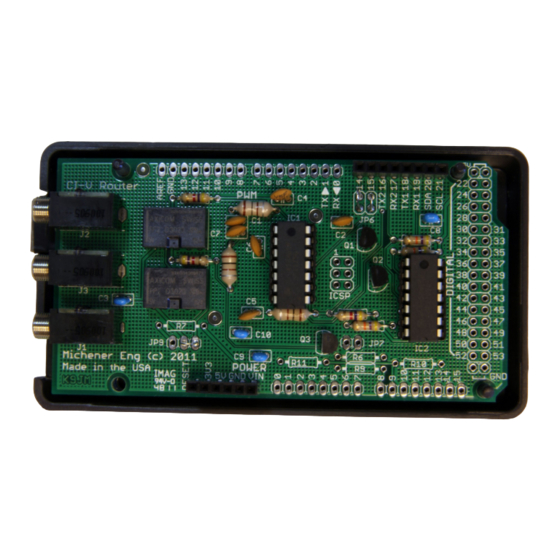
Illustration 1: CI-V Router Shield for the Arduino Mega 2560
The K9JM CI-V router is an Arduino stand alone computer, an Icom CI-V interface "shield" and
software. The CI-V Arduino shield board is the board shown above. The software, both source
code and prebuilt, ready to load binary code is available on the K9JM.com website.
K9JM CI-V Router User Guide
for software version 1.11
March 2015
Page 1
Advertisement

Summary of Contents for K9JM CI-V
- Page 1 Illustration 1: CI-V Router Shield for the Arduino Mega 2560 The K9JM CI-V router is an Arduino stand alone computer, an Icom CI-V interface "shield" and software. The CI-V Arduino shield board is the board shown above. The software, both source code and prebuilt, ready to load binary code is available on the K9JM.com website.
- Page 2 The external power supply is handy when the router is in use when the computer is off. Note: If the CI-V router is powered down, a relay connects all the CI-V bus together, so communications between units will still occur, without the "protection"...
- Page 3 IMPORTANT: The router at first opportunity after reset builds a table of discovered equipment on each port. IF you move anything from port to port of the CI-V router it is advised to RESET the CI-V router. This is done by hitting the reset button, or turning the router off by removing all power sources, including the USB.
-
Page 4: Getting Started
Getting started There are six steps that are necessary to get the CI-V Router up and running: 1. Installing Arduino USB Drivers (Windows only) 2. Downloading CI-V software to the Arduino board 3. Configure the CI-V Router 4. Configure your ICOM Radios 5. - Page 5 Note: If you have a Rev3 board properly installed, on the above "Computer Management" screen will read "Arduino Mega 2560 R3 (COM#)" If you are running Windows, and if the Arduino is connected to the PC, it should be visible in your computers "Computer Management"...
- Page 6 And select the desired COM Port number in the highlighted box If the port is marked "IN USE" and it is a "virtual" COM device that is currently not in the machine, select it to take over that device. If you have a physical COM port that you wish to re-assign to another number, thus freeing that COM port on your machine, select the device in the device manager, right click on "Properties"...
- Page 7 There are many YouTube.com videos that detail step by step how to install drivers for the Arduino that may be useful. STEP TWO: Uploading CI-V Router software If you have a complete unit, software was installed before shipping, skip this step. If you ever wish to install the latest software, for any reason, follow this proceedure.
- Page 8 To learn how to do this read up on the Arduino site. If you do not wish to configure the router, re-attach the CI-V "shield" on the Arduino board. STEP THREE: Configuring the CI-V Router NOTE: When touching the Arduino and CI-V router electronics be sure to employ anti-static proceedures.
- Page 9 On a virgin Arduino board or any completed system shipped, the configuration will be in the default state. The baud rate for the CI-V ports is 9600 and 38400 for the USB 'computer'. To confirm or change these parameters, the following proceedure can be followed.
- Page 10 Note: These settings do not represent the default setting as shipped. The first line will tell you the version and date of the current CI-V router software. The second line tells the amount of free static RAM available for the program to use. The board has 8K bytes.
- Page 11 The default is 38400, which is supported by many programs. The baud rate for the CI-V bus is the baud rate for each of the three CI-V ports. If using a Icom PW-1 amplifier Icom recommends a baud rate of 9600. If your radio support "auto", baud rate, do not run operate the radio in the "auto"...
- Page 12 Remember to remove the jumper from Pin 53 and to reseat the CI-V "shield" on the Arduino. The two pins just below pin 52 and 53 on the Arduino board are ground. This is a handy place to store the jumper when not configuring the router.
- Page 13 3. Transceive 4. CI-V with IC-731 Make sure the baud rate matches the baud rate as configured for the CI-V router. Recommend 9600 baud. Note the address. If there is more than one radio, make sure the addresses are different. The address will be required when configuring PC client software.
- Page 14 Make sure the Icom Code matches the Address of your radio. PTT commands can be used over this interface, if supported by your radio. Page 14...
- Page 15 The N1MM manual states that users shall " "CI-V Transceive" to OFF - If CI-V is set to ON, the Bandmaps will not update as the VFO is turned. This statement is true. If N1MM gets "Transceive" messages, it really slows down the band map.
- Page 16 Set the proper COM Port and radio type in the "Configurer" window, the click on "Set" for the details. Again DTR and RTS should be off, 8 bit, 2 stop bit. Make sure the Icom code matches the code for the radio which is to be controlled.
- Page 17 Again configure the baud rate to match the CI-V computer baud rate and again select the COM port to match the port of the CI-V Router. All other settings can be configured as desired. More information on .ini file settings and configurations are available in the WriteLog manual.
- Page 18 Icom, with most modern radios being covered by the 'Icom" entry for 'Select Rig'. Again select the COM port and baud rate for the computer port of the CI-V router. Select the proper baud rate, 8 bits, no parity, 2 stop bits, connection power = NONE, and any polling rate.
- Page 19 Once you see things working, hit the 'Done' button and you're good to go DX4WIN To use DX4Win you must use CI-V router software version 1.02 or higher. These tests were done with version 8.05 of DX4WIN. There is no need for a resistor to pull up the reset line.
- Page 20 VERY IMPORTANT: For versions of Ham Radio Deluxe less than version 6.2, the max baud rate is 19200. If you plan to use this program, the computer port on the CI-V Router configuration must be set to 19200 or below, and all other PC programs must be set to this baud rate.
- Page 21 At the 2014 Visalia DX Convention I sat down and talked with the developer of HRD. I talked him into changing the program to support the K9JM Router. I also bought a copy of the program. Starting with version 6.2 released in mid May 2014, the program now supports 38,400 baud.
- Page 22 Make sure there is only one radio on a COM port. See Above. This is how the Arduino appears in the serial port window as COM6. See Below: Page 22...
- Page 23 TRX Manager I know very little about TRX Manager, but I did download and install the "Demo" version 4.6.5 Set up is had by going to the Menu item Parameters and selecting "SetUp" Page 23...
- Page 24 RTS and DTR Enabled boxes MUST BE UNCHECKED! CAT speed must be set to the same speed as the router Computer baud rate. TRX Port must be set to the COM port for the CI-V router. TRX-Manager supports only COM 1 through 15, odd for a program that supports so many devices.
- Page 25 I worked with version 2.20f demo version, and received help from Pat KG4URP. For configuration, I would recommend the following as well as using version 1.09 or greater CI-V Router software. Set up is fairly straight forward. On the menu, select 'Configure' then TRCVR CAT/PTT...
- Page 26 Select the proper ICOM model, set your favorite defaults, then hit 'Details' button. Again in my configuration, the CI-V router is on COM6. Again two stops bits and RTS and DTR are always off. You should be off and running.
- Page 27 (which provides the CI-V bus). First, while there are two CI-V connections on the back of the PW-1, there is only one CI-V bus. The two connectors on the back of the PW-1 are wired together. The CI-V connection to the radio can be made to either jack.
- Page 28 For synchronization the CI-V router does NOT have to be operational. It should be cabled up, but power on the computer and CI-V router should be off. Make sure all radios are configured to the same baud rate (9600) and CI-V Transceive is set to "ON".
-
Page 29: How Does It Work
Router PW-1 The heart of the CI-V router is an Atmel microprocessor on a Arduino Mega 2560 board. It is a stand alone 16 MIP computer that runs a program that is located in it's internal 256K of flash memory. The key feature of this processor is that it has four hardware serial ports. It is capable of listening to and send to four serial ports at the same time without missing a byte. -
Page 30: Configuration Settings
When powered down, the router connects all CI-V port together. If there are only two devices on the CI-V side of the router, there is lesser chance of a collision that will cause harm. It is advised to keep the router powered whenever anything connected is on. This relay bypass option provides functionality if the router is powered from the USB and the host computer is turned off. - Page 31 PC logging software and to other equipment connected to the CI-V bus. This optional feature should be used with great care if your software does this, to assure that the Linear amplifier (e.g. PW-1) does not hot switch between bands while transmitting. This is the default operation of previous versions of software.
- Page 32 Introduction One feature of the K9JM CI-V router is the ability to store a table of driver (exciter) power level as a function of frequency. If enabled, the router will generate a command to the ICOM radio to set the power pot whenever the radio tunes to a different band segment.
- Page 33 How does it work? Within the K9JM CI-V router is stored a table of relative power level for each of band segment. The power level is a byte value (0 .. 255) which corresponds to the relative position of the RF Power ad- justment on the radio.
- Page 34 12-Icom radio CI-V address 0x64 hex 13-Reset all to default values NOTE: The entry of the CI-V address can either be done in decimal (base 10) or hexadeci- mal (base 16). The program will interpret a string starting with '0x' (zero x) as being hexa- decimal.
- Page 35 255 or 100%, the driver/exciter will be at maximum power. Config CI-V Router 1 -Computer baud rate = 38400 2 -CI-V baud rate = 9600 3 -Transceive msg to other radios = True 4 -Transceive msg to USB = True...
- Page 36 Select band 1..23 0 or Enter to Return and Save: ? Config CI-V Router 1 -Computer baud rate = 38400 2 -CI-V baud rate = 9600 3 -Transceive msg to other radios = True 4 -Transceive msg to USB = True...
- Page 37 17 - 1992KHz -> 2000KHz = 0 0.0% 18 - 3500KHz -> 3525KHz = 0 0.0% 19 - 3525KHz -> 3550KHz = 0 0.0% 20 - 3550KHz -> 3575KHz = 0 0.0% 21 - 3575KHz -> 3600KHz = 0 0.0% 22 - 3600KHz ->...
- Page 38 It is good to expand the window size for the serial communications program so as to view a longer view. In the configuration menu make sure that the CI-V baud rate is set correctly, then select 10: 10– Driver power table ......
- Page 39 8 -Enable driver power level = False 9 -Enable driver power level learn = False Note: To enable either of these parameters, the Icom radio CI-V address must be set. If "Enable driver power level" is true, then the router will send an RF Power command to the radio every time the radio is tuned to a new band segment.
- Page 40 When the router is started with Pin 52 grounded, a simple program runs that tries to send a message from each CI-V port to the other CI-V ports every 100ms. To see the results, one must use PuTTy (or your favorite communications pro- gram) to connect to the router at 115200 baud rate through the USB port.
- Page 41 For this program, the ports are numbered 1, 2 and 3. Where port one is the CI-V port closest to the USB connector. Port 2 is in the middle, and Port 3 is the port closest to the coaxial DC power con- nector.
- Page 42 Available at http://k9jm.com/CIV_Router/CIVSniffer.zip In the zip file is a detailed description of how to use the tool. It permits one to use any CI-V interface to make their PC into a CI-V message monitor, sniff out messages. Transceive messages: All Icom radios have a setting called "Transceive" on/off. When on, the radio to sends a "transceive"...
- Page 43 The CI-V router can pull well over 100ma to ground, so it can easily handle the extra current. Icom does not specify the loading of the CI-V bus, but in general each node on the bus should pull up at least enough to provide it's own input current.
-
Page 44: Warranty
ICOM USB Driver software. Suggestion by Ken Goodwin K5RG Common Error: The PW-1 has two 'remote' or CI-V that are internally are wired together. Do NOT wire each of these to a separate port of the router. Acom 2000 I have worked with Bill, N3RR getting the K9JM router to work with an Icom radio and the Acom 2000 amplifier.
Need help?
Do you have a question about the CI-V and is the answer not in the manual?
Questions and answers