Table of Contents
Advertisement
Quick Links
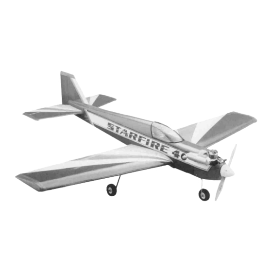
STARFIRE 40
Almost-ready-to-fly Radio Controlled Model Airplane
• Superior quality in an Almost-Ready-to-Fly model
• 80% complete out of the box - No Sanding, Painting, or Finishing required.
• Beautiful sporty appearance.
• Super acrobatic aircraft for experienced pilots
• All wood construction with sheeted wings
• Fuel Tank, Spinner, Wheels, Landing Gear, Engine Mount, and Hardware are included.
RADIO: 4 channel (not included)
ENGINE: .40 Performance 2-cycle (not included)
or .61-.91 4-cycle (not included)
ACCESSORIES: Standard field equipment (not included)
ENTIRE CONTENTS © 1991, HOBBICO , INC.
WINGSPAN: 55 1/2 in.
LENGTH: 49 3/4 in.
WING AREA:
534sq.in.
WEIGHT: 5 1/2 pounds
V1.0
Advertisement
Table of Contents

Related Manuals for Hobbico starfire 40


Summary of Contents for Hobbico starfire 40
- Page 1 LENGTH: 49 3/4 in. WING AREA: 534sq.in. WEIGHT: 5 1/2 pounds RADIO: 4 channel (not included) ENGINE: .40 Performance 2-cycle (not included) or .61-.91 4-cycle (not included) ACCESSORIES: Standard field equipment (not included) ENTIRE CONTENTS © 1991, HOBBICO , INC. V1.0...
- Page 2 .40 Sized 2-Cycle Engine............1 .61 - .70 Sized 4-Cycle Engine..........1 4 - Channel Radio System..........1 Pacer PlastiZap CA Glue............1 Goldberg #481 Foam Rubber ..........1 Hobbico (HCAR3950) 30-Minute Epoxy......1 Silicone Sealer..............1 Dubro 121 E-Z Connects (Optional)........2 Hobbico (HCAR3760)Threadlock........1 O.S. 70 Surpass O.S.
-
Page 3: Table Of Contents
PARTS LIST Before assembly, match the parts in the photo on this page with the parts in the kit. Check off each part as they are located. If any parts are missing or damaged, consult your hobby dealer. ( ) 1 Fuselage......1 ( ) 21 Front Gear Strut...! ( ) 41 Neoprene Ring....1 ( ) 2 Right Wing.....1... -
Page 4: Ailerons
WING ASSEMBLY Trial fit the 7mm dowel rods into the holes and butt them up against the front spar They should be positioned straight in and parallel to the wing root Once satisfied with the fit, epoxy them in place using slow cure epoxy. Next, using a sanding block sand the wing roots of both w i n g On both wing halves, make a mark exactly 1 from the wing root halves to ensure that they are perfectly flat Be careful not to... -
Page 5: Hinges
IMPORTANT! The f o l l o w i n g t w o steps are critical in the assembly of this kit. If they are not done correctly, wing failure could result Be sure to use plenty of slow cure (30 min) epoxy Install the wing center cover using Plastizap CA Glue Wipe 6 Check the w i n g j o i n e r to find the angled sides Place the joiner on off any excess glue immediately Next on the f r o n t o f t h e... -
Page 6: Blind Nuts
12. Check the ailerons for smooth operation. By exercising the 15. Glue the three wing mounting blocks together using slow cure ailerons after the glue is cured, you can loosen any of the stiffness epoxy. Center the three blocks together by lining up the holes. The larger block should be at the bottom. -
Page 7: Landing Gear Installation
21. Place the two 4mm washers onto the 4 x 30mm screws and push 18. Thread the wing screws into the blocks so that the heads are 3/8" them through the wing from the bottom side. Next, slide the above the block. Apply ink or paint to the heads of the screws. Proceed with the next step immediately before the ink or paint rubber 0-rings onto the screws. -
Page 8: Main Gear Struts
Feel along the front edge of the blue stripe until you find the two Temporarily install the strut and mark the bottom of the fuselage slots under the covering, trim out the covering over the slots. for the installation of the control rod Mark the hole about 1" from the firewall and 7/8 from the left bide of the fuselage. -
Page 9: Wheel Collars
Make a Z-bend on one end of the 450mm control rod. Install the Temporarily install the two mounting plates onto the mount so front strut with the rod and secure with a collar and a 3 x 5mm the engine will angle slightly to the right for 2 degrees. Tighten the screws only until they seat so that you can still move the screw. -
Page 10: X 15Mm Screw,
Mount the engine to the mounting plates using four 3 x 15mm 7. Install the throttle control rod on the throttle arm of the engine. screws, four lock washers, and four 3mm nuts as shown. Note: Use thread locking compound on the screws and nuts to prevent them from loosening under vibration. - Page 11 Install one of the long and one of the short fuel pipes through the Attach the completed fuel tank cap to the tank. Make sure that rubber cap. Center the pipes in the cap and place the two plastic the bent pipe is pointing to the top. Slide the cap on until the lip discs onto each side.
-
Page 12: Radio Installation
Install the completed tank into the fuselage. Route the fuel Screw the aileron horns onto the aileron arms. Make sure you use tubing through the hole and push the tank cap through until the two horns with the larger holes. seated. - Page 13 Attach the clevises to the aileron horns and slide on the retaining Connect the aileron servo to the receiver and check the movement tubes. After checking the neutral position of the aileron servo of the ailerons. Make sure that both ailerons are neutral when and ailerons, put a mark on the push rods (scratching with a the servo is neutral.
-
Page 14: Push Rod Exits
11. Bend the three long rods as shown for the elevator and rudder. 14. Next, do the same with the rudder push rod. Make sure that each Note: the pre-bent rods will be used later in step 13. rod fits in the groove Now slide the four pieces of shrink tubing over the ends of the wooden rods and shrink them with a heat gun or lighter To ensure durability, place a drop or two of Cyanoacrylate glue on the edges of the shrink tubing... -
Page 15: Tail Assembly
17. Slide the throttle rod through an E-Z Connector and attach to the Trim out the covering and the wood piece at the tail of the plane. servo arm. With the throttle at low position, pull back the rod and tighten the screw on the connector. Plug the throttle servo into the receiver and check for proper operation. - Page 16 When the stabilizer is perfect, draw a line with a sharp pencil on Measure the rear fuselage to find the center. Draw a line along both sides top and bottom (4 lines total). center. Apply slow cure epoxy to the line and the bottom of the vertical Remove the covering between the lines using a hobby knife.
- Page 17 10 Trial fit the turtle deck onto the fuselage and check for a good fit Glue on the control surfaces with slow cure epoxy and allow to Once satisfied with the fit attach the turtle deck to the fuselage cure Check the operation of the elevator and the rudder to using Plastizap CA glue Be careful not to use to much glue ensure smooth performance If they seem stiff, continue to exercise until they loosen up...
- Page 18 16. Drill six 1/16" holes at the marks. Make sure to drill straight in 19. Align the control rods over the respective servo horns and make a through to the other side and mount the three horns to the mark where they intersect. Make sure that the control surfaces surfaces with the 2 x 20mm screws.
-
Page 19: Cowl Installation
Cowl Installation Position the cowl in place and drill two 2mm holes 1 1/2 apart on each side and install the 2 5 x 10mm S/T screws to secure the cowl in place Attach the muffler and pressure line Final Assembly Lightly sand the flanges on the left and right cowl edges This will allow the glue to adhere better to the plastic Next hold or tape the right side over the flange of the left side and glue... -
Page 20: Center Of Gravity
Next, carefully apply the decals to the cowl and the turtle deck. Route the antenna through the hole in the fuselage and through the hole in the tail. Use the plastic retainer and secure the wire Use the box lid for a reference. to the tail. -
Page 21: Take Off
(like • Check and double check that the transmitter and receiver switches the Hobbico Flightstar 40) and become proficient with it before are switched to the off positions attempting to fly the Hobbico Starfire 40 •... -
Page 22: Starting The Engine
STARTING THE ENGINE ENGINE MAINTENANCE Turn the radio system on and open the throttle to full open. Place your finger over the air intake on the carburetor while turning the prop counter-clockwise a few times Watch the fuel Always check the engine mounting bolts, muffler, glow plug, propeller line If no fuel is reaching the carburetor, recheck the fuel line and spinner, etc , before attempting to start the engine Check for... - Page 23 IMPORTANT SAFETY MEASURES TRANSPORTING CHECKLIST Before leaving for the flying field go though the checklist. This will RECEIVER BATTERY help prevent you from forgetting to take things with you. Always make sure the receiver battery pack is fully charged before flying Wrap the receiver battery in 1/2"...
- Page 24 HCAA2600 - ASAP Extra 300 HCAA2010 - AWARF Avistar 40 HCAA2650 - ASAP P-40E Warhawk HCAA2100 - AWARF Hobbistar 60 HCAA2050 - AWARF Flightstar 40 HCAA2580 - ASAP Telestar 40 HCAA2520 - ASAP Telestar 25 Entire contents © 1991 .HOBBICO , Inc.
Need help?
Do you have a question about the starfire 40 and is the answer not in the manual?
Questions and answers